• Home
  • Download PDF
  • Order CD-ROM
  • Order in Print

Home > United Facilities Criteria CD 2 > > Figure 3-8. Section B-B of Raised Cover Plate
Figure 3-7. Section A-A of Raised Cover Plate
Figure 3-9. Section C-C of Raised Cover Plate

 Heating and Cooling Distribution Systems
Page Navigation
  52    53    54    55    56  57  58    59    60    61    62  
CEMP-E
TI 810-32
10 January 2002
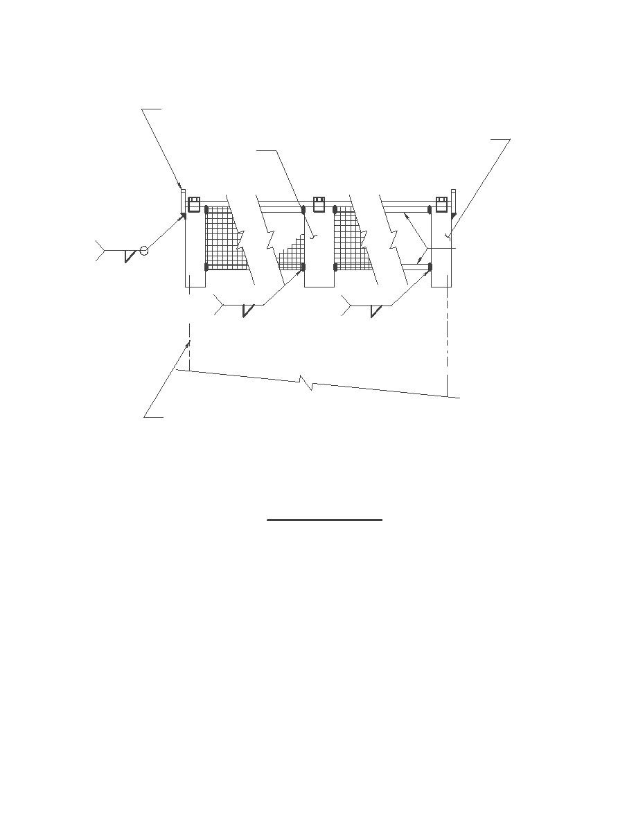
LIFTING LUG DETAIL (TYP.)
(SEE FIGURE 3-11)
1'-4"X6"X 5/16 " CORNER PLATE
1'-4"X6"X 5/16 " SUPPORT
(8 REQ'D PER ASSEMBLY)
PLATE (SEE NOTE 2 ON
FIGURE 3-13)
ANGLE FRAME
TYP.
5/16
TYP.4 PLACES
TYP.
PER PLATE
2
2
1/4
1/4
OUTSIDE CONCRETE VALVE
MANHOLE WALL (TYP.)
SECTION B-B
NO SCALE
Figure 3-8. Section B-B of Raised Cover Plate.
3-15


Western Governors University
< Previous Page
Index ^
Next Page >

Privacy Statement
Press Release
Contact

© Copyright Integrated Publishing, Inc.. All Rights Reserved. Design by Strategico.