TM 5-848-1/AFM 88-12, Chap.1
formulas, demand is usually expressed in cubic feet
well. Consideration must, however, be given to dif-
per hour. Because of the variability of the volume
ferences in inside diameter. In the larger pipe sizes,
of gas with changes in pressure and temperature,
plastic pipe wall thicknesses are likely to be greater
reference to definite bases of pressure and
than those of steel pipe.
e. Distribution system flow equations.
temperature is necessary in expressing quantities
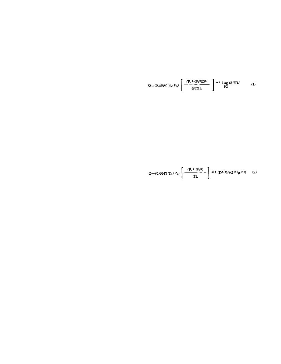
(1) Fully turbulent flow (rough pipe flow law).
volumetrically. It is essential that the stated
characteristics of the gas, the computations of the
The equation for fully turbulent flow is as follows:
connected appliance loads, and the flow formulas
used in the design of the pipe system, all be on the
same basis. Base conditions are 60 degrees F and
14.73 psia in accordance with AGA Orifice Meter-
ing of Natural Gas, Report No.3.
b. Flow conditions. There is a pressure loss in
(2) Partially turbulent flow (smooth pipe flow
pipes roughly proportional to the square of the ve-
law). Any of the accepted gas flow equations used
locity; and there are at least two distinct flow re-
gimes in pipes, laminar, and turbulent. There is a
with steel pipe, such as Mueller, Pole, or the IGT
distinct discontinuity in behavior of fluid when
Distribution Equation, can also be used for calcula-
laminar flow rates are exceeded, and a large region
tion of plastic pipe flow capacities. Those equations
for mixed flow behavior (partially turbulent flow)
which yield conservative values for steel pipe will
exists between the upper limit of laminar flow and
also be conservative for plastics. The IGT Distribu-
the behavior of pipes in fully developed turbulent
tion Equation is thought to be representative of
flow. The exact transition regions between the
both steel and plastic for most distribution design
various flow regimes are not yet accurately
situations. It is as follows:
predictable for the various fuel gas piping situations
of practical importance. Gas engineering practice
has developed practical approximations at working
around this inadequately defined area. In only very
unusual situations is this lack of exactness of any
practical or economic importance.
c. Distribution system design criteria. The dis-
(3) Definition of terms. The terms used in the
tribution system design engineer rarely designs a
flow equations above are:
totally new system. The design will generally con-
D = inside pipe diameter, inches
sist of changes to an existing system. Even a new
G = specific gravity
system, unless it is for a complete camp, base or
L = length of pipe section, feet
other military facility, has unpredictable loads. The
Pb=base pressure, 14.73 psia
most compelling problem for the distribution
P1 = upstream pressure, psia
system designer is the infrequency of the system
P2 = downstream pressure, psia
operation at or near design capacity.
Q = gas flow rate, MSCFH (thousands of
d. Flow of natural gas in pipelines. Plastic pipe
standard cubic feet per hour)
has a very smooth and slippery surface. Its fric-
Tb=base temperature, 520 Rankine
tional resistance is considerably less than that of
steel pipe. Therefore, it is often assumed that plas-
T = average temperature of flowing fluid,
tic pipe has significantly more flow capacity than
Rankine
steel pipe. This assumption would be correct under
Z = average compressibility factor
fully turbulent flow conditions, such as those en-
= viscosity, lb/ft-sec
countered in water service. However, investigation
K = effective roughness of pipe surface,
of flows in natural gas distribution systems indi-
inches
cates that the design flows usually fall within the
= 0.00006 inch for plastic
range of only partially turbulent flow (see table 1
= 0.0007 inch for steel
for an indication of the typical flow rates in gas
= 0.01 inch for cast iron
distribution systems). In this range, the smooth-
(4) Using the flow formulas. Figure 1 may be
pipe flow equations apply all the time to both plas-
used to determine whether the rough pipe or
tic and steel; therefore, the pipe wall roughness is
smooth pipe flow law should be used. If the flow
not a significant factor. Flow formulas found to be
rate expected is above the curve, then the rough
satisfactory for sizing steel pipe in natural gas
pipe law should be used. If flow rate falls below the
service are recommended for sizing plastic pipe as
7


 Previous Page
