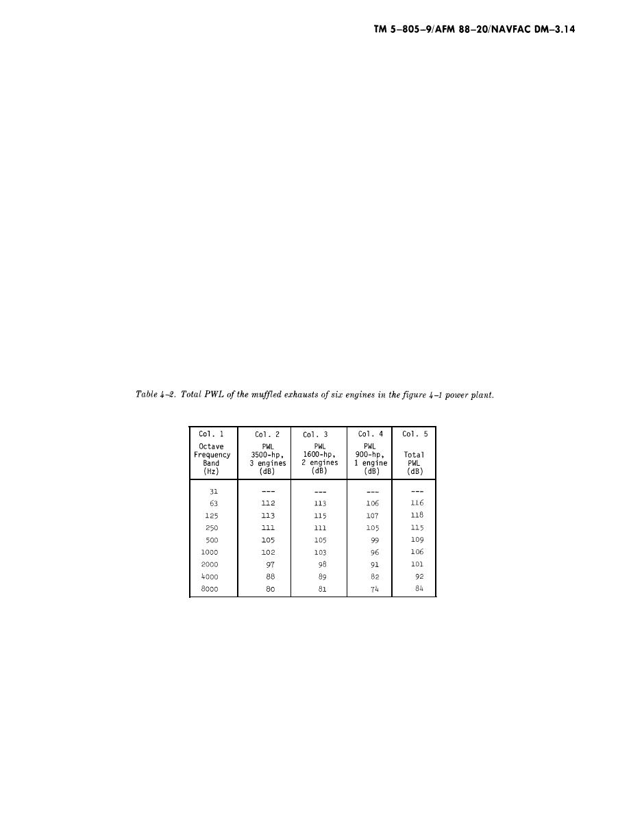
This simplified approach yields a "marginal" rat-
treatment should follow the recommendations giv-
ing, whereas the more detailed analysis of figures
en for a category 4 or 5 office or work space (N&V
420 and 421 produces an "acceptable" rating for
table 32) located within 20- to 80-ft. distances of
the six large engines in this power plant. For such
the same structure. The detailed approach is nor-
close distances, there is no guarantee that NC40
mally preferred because it takes into account the
levels can be reached in the low-frequency octave
more specific design components, and, in this case,
bands. Earthborne and structureborne vibration
includes the influence of the sound absorption ma-
terial in the corridor ceiling--which could just
decays slowly with distance (N&V para 4l), espe-
cially at low frequency. If this were a critical prob-
about eliminate the noise excesses that appear in
item 12 of the figure 4-22 simplified analysis.
lem, it would be advisable to move the offices to
greater distances from the power plant. In this
(d) A similar analysis carried out for the
sample problem, it is assumed that the office occu-
right-side office and the secretary's office would
pants are involved with the operation of the power
show slightly lower sound levels because of the
smaller wall area facing the corridor. Thus, any
plant and would be receptive to a moderate amount
of noise and vibration.
wall design that meets the acoustic requirement for
the left-side office will be acceptable for all other
(9) Engine exhaust noise to on-base housing.
spaces along the corridor.
(a) On-base housing is to be located 1200 ft.
(8) Vibration control for the offices. These of-
to the east of the power plant, and it is desired to
fices are located only about 20 ft. from the nearest
not exceed NC25 sound levels indoors at the hous-
engines. This imposes fairly serious vibration isola-
ing. PWLs of muffled engine exhausts are given in
t i o n requirements to meet the NC40 low-
figures 42 through 44. The top of each exhaust
frequency sound levels in the offices. Paragraph
pipe extends above the roof of the power plant and
36 contains details of vibration isolation of
is in unobstructed view of the housing. The PWLs
reciprocating engines. The vibration isolation
of the six engine exhausts are given in table 42.
(Appendix B of the N&V manual describes "decibel
The PWL contributions are obtained from Item 21
in figures 42, 43, and 44. Where two similar en-
addition.")
(b) SPLs inside the base housing are esti-
gines are involved, 3 dB are added to the levels of
mated with the use of DD Form 2302 (Estimated
one engine (as in CO l. 3, taken from fig. 4-4); and
Outdoor and Indoor SPL at Neighbor Position
where three similar engines are involved, 5 dB are
Caused by an Outdoor Sound Source Whose PWL
added to the levels of one engine (as in COl. 2, taken
is Known). A sample calculation is given in figure
from fig. 42). The total PWLs of all six engine ex-
4-23.
hausts are given in the last column of table 4-2.
4-33


 Previous Page
