The engine is housed inside the enclosure of the en-
and table 39). If a longer muffler (greater in
tire engine-generator package, which is assumed to
length than 1.5D in fig. 31) is later found necessa-
have approximately the noise reduction of the type
ry, this turn may qualify as a Class 2 lined bend,
5 enclosure of table 27. Both the air intake and
with a slight improvement in insertion loss. The
exhaust stacks are oriented vertically and have the
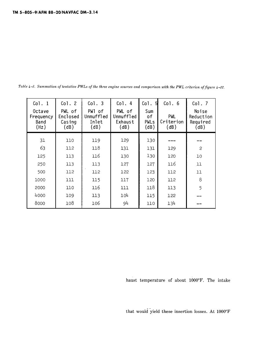
tentative PWLs of the three sources are given in
horizontal directivity effect shown for the 90 angle
Items 6, 13, and 20 of figure 433, without the in-
in table 28. Each stack will be fitted with a muf-
sertion losses of the intake and exhaust mufflers.
fler, whose insertion loss is still to be determined,
In table 43, these three PWLs are added together
but the muffler and the 90 turn into the engine
and compared with the PWL criterion developed in
figure 4-32.
will provide at least a Class 1 lined bend (fig. 31
The last column in table 43 shows the amount of
the 2000- and 4000-Hz bands, and the engine casing
noise reduction required for the total plant to meet
noise is fairly close to the PWL criterion in the 250-
the criterion PWL. If in any given octave band all
through 2000-Hz bands. This implies that all three
three engine components contribute significantly to
sources may have to be quieted for the entire plant
the total noise, some of the sources must be qui-
to meet the criterion.
eted more than the column 7 amount, so that the
total of the three components does not exceed the
d. Mufflers for engine intake and exhaust.
column 6 criterion. This point is illustrated by look-
(1) Table 4-3 shows that the engine exhaust
ing at the 500-Hz values, for example. If each
will require a muffler that should have insertion
source alone is quieted to just meet the 112-dB cri-
loss values of at least 2 dB at 63 Hz, 10 dB at 125
terion value, the total of the three quieted compo-
Hz, and 11 dB at 250 and 500 Hz, at an elevated ex-
nents would be 117 dB, or 5 dB above the criterion
level. Thus, the three sources must be quieted to
muffler should have insertion loss values of about 2
such an extent that their new total ("decibel sum")
or 3 dB at 125 Hz, about 3 to 5 dB at 250 Hz, and
will just equal 112 dB. From table 43, it is seen
about 5 to 10 dB in each of the 500- through
that the engine exhaust is clearly the dominant
2000-Hz bands. Tables 33 through 38 may be
source in the 31- through 500-Hz octave bands, the
used to approximate the dimensions of mufflers
engine intake noise exceeds the exhaust noise in
4-50


 Previous Page
