TM 5-811-7
(d) Calculate the total resistance (eq 2-15):
RT = Ra + Rw + Rc
RT = 1.46 ohm + 0.0795 ohm + 0.212 ohm
RT = 1.75 ohms.
(10)
Calculate the rectifier voltage from equation 2-16:
v(rec) = (I)(RT)(150%)
v(rec) = (2.36 A)(1.75 ohms)(150%)
v(rec) = 6.2 V.
c. Select rectifier. Based on the design requirement of 6.2 volts and 2.36 amperes, a rectifier can be
chosen from those marketed. After a rectifier has been chosen, the system's cost can be calculated in
accordance with paragraph 2-2. A comparison with other anode sizes and types will yield the most
economical design.
D-3.
Heating distribution system.
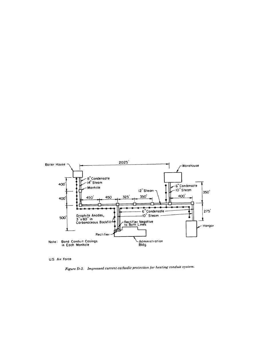
Impressed current cathodic protection is designed for a well coated, buried heating distribution system as
shown in figure D-2. The distribution system has not yet been installed, so measurements cannot be made.
Rectifier size need not be calculated, because it is sized in the field after anode installation.
a.
Design data.
(1) Average soil resistivity is 1000 ohm-centimeters.
(2) Design for 80 percent coating efficiency based on experience.
(3) Design for 4 milliamperes per square foot of bare metal heating conduits.
(4) Groundbed resistance must not exceed 1.5 ohms.
(5) Graphite anodes must be installed with carbonaceous backfill.
(6) Design for a 15-year life.
D-4


 Previous Page
