UFC 3-580-10
14 July 2004
Including changes 12 April 2005
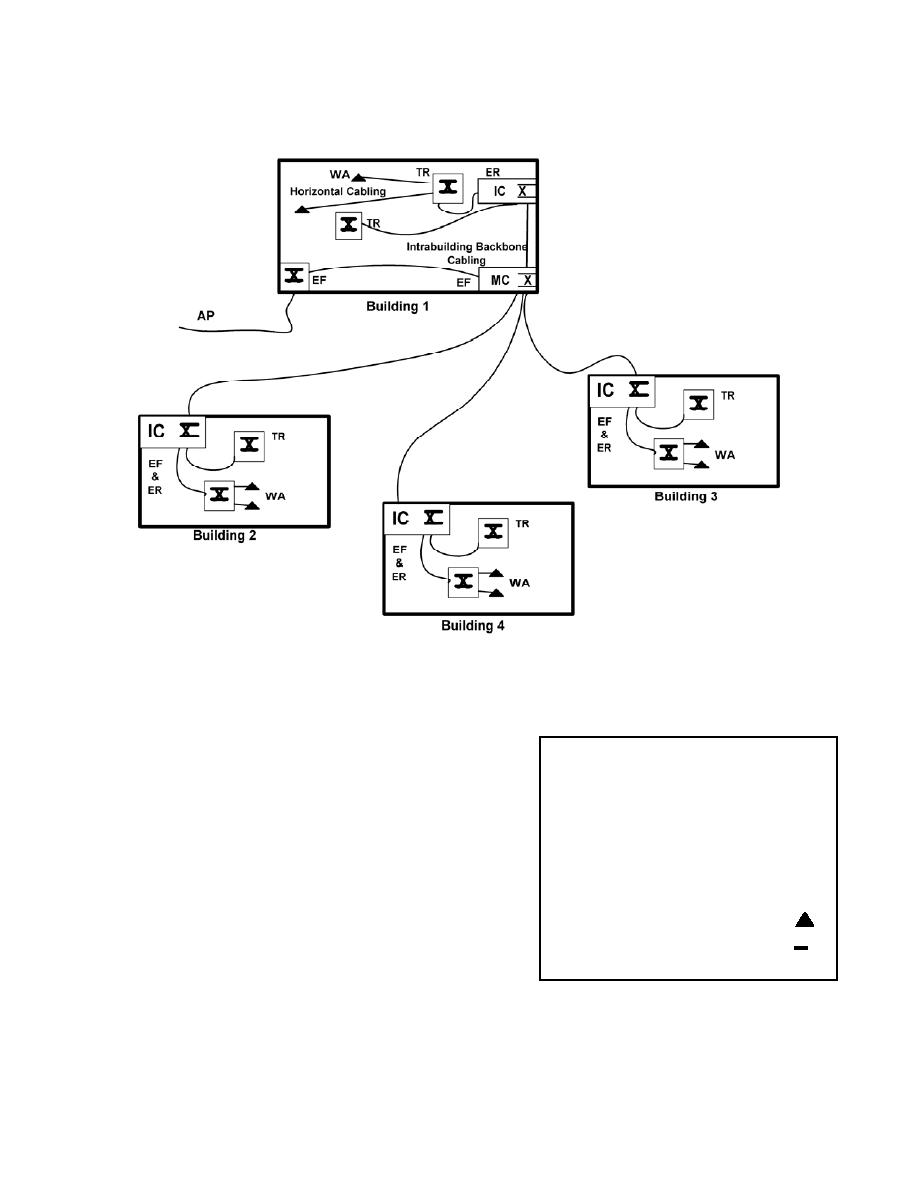
Figure B-1 Single Line Drawing of EIA/TIA Facility/Function Terminology
NOTES
1. This figure is not meant to be an all-inclusive
Legend
representation of the telecommunications
cabling system and is provided only as a
Access Provider ......................... AP
typical example.
Entrance Facility........................ EF
Equipment Room....................... ER
2. All cross-connects located in the
Intermediate cross-connect ......... IC
telecommunications rooms (TRs) in this figure
Main cross-connect................... MC
are horizontal cross-connects (HC's).
Telecommunications Room....... TR
3. The equipment room (ER) for the POP would
Work Area ............................... WA
be connected to the access provider (AP) as
Telecommunications outlet .........
in Building 1 in the example.
Cross connect .............................. X
4. NMCI terminology/function has been limited to
EFs and TRs. The function of the ER is
included within the EF or TR.
40


 Previous Page
