UFC 3-600-01
26 September 2006
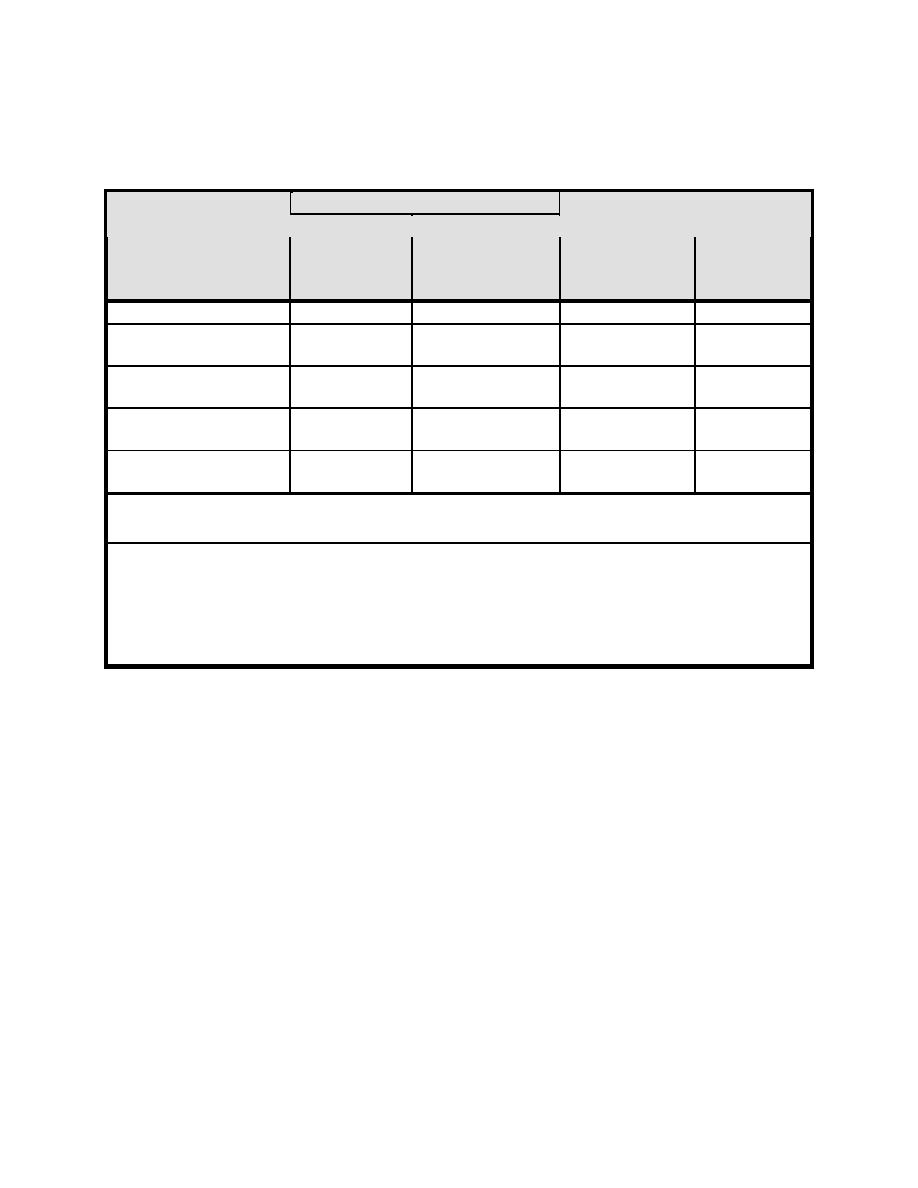
Table 4-1 Sprinkler System and Water Supply Design Requirements for
Sprinklered Facilities
SPRINKLER SYSTEM
HOSE
DURATION
DESIGN
DESIGN AREA
OCCUPANCY
STREAM
OF
m (ft) b
DENSITY
CLASSIFICATIONa
ALLOWANCE
SUPPLY
L/min/m
L/Min (GPM)
Minutes
(GPM/ft)
Light Hazard
4.1 (0.10)
280 (3000)
950 (250)
60
Ordinary Hazard
6.1 (0.15)
280 (3000)
1900 (500)
60
Group 1
Ordinary Hazard
8.2 (0.20)
280 (3000)
1900 (500)
90
Group 2
Extra Hazard
12.2 (0.30)
280 (3000)
2840 (750)
120
Group 1
Extra Hazard
16.3 (0.40)
280 (3000)
2840 (750)
120
Group 2
a
Refer to Appendix B for occupancy hazard classification.
b
See paragraph 4-2.3.3.
Note: The protection requirements identified in Table 4-1 are based on standard commercial
practices followed throughout civilian industry for highly protected risk (HPR) properties. Table
4-1 represents the minimum requirements necessary to establish minimum comprehensive life,
mission, and property loss prevention. Table 4-1 was adapted as a result from detailed studies
by Factory Mutual of loss experience from 1956 to 1965, loss experience in selected
occupancies from 1966 to 1977 and from 1981-1990, and fire test data.
4-2.3.3
Sprinkler Design Area Adjustments.
4-2.3.3.1
For dry pipe systems, the design area of sprinkler operation in
Table 4-1 must be increased by 30 percent as required by NFPA 13.
4-2.3.3.2
The design areas in Table 4-1 must be increased by 30 percent for
sloped ceilings that exceed a pitch of one in six, as required by NFPA 13.
4-2.3.3.3
When NRTL listed quick-response sprinklers are used throughout
the system, the design area in Table 4-1 may be reduced as permitted in NFPA
13, without revising the density in Table 4-1.
4-2.3.4
Quick Response Automatic Sprinklers.
The use of quick response automatic sprinklers (QRAS) is limited to wet pipe
systems.
4-2.3.5
Hydraulic Calculations.
31


 Previous Page
