UFC 4-023-03
25 January 2005
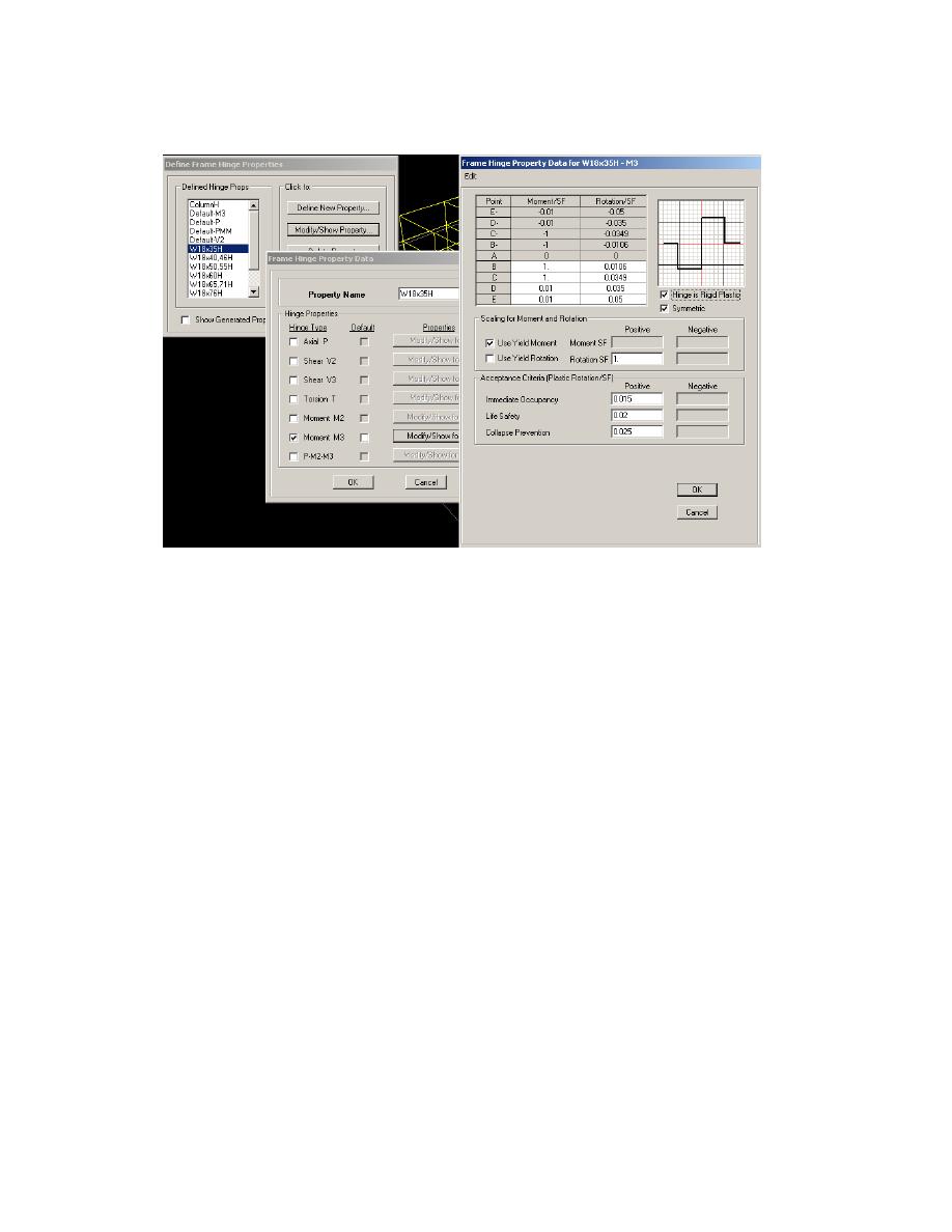
Figure D-8 Input Screens for Nonlinear Hinge Properties
D-5.4
Define Nonlinear Analysis Cases.
1) Add new analysis case for each column being removed and for each wind
direction. For this example, eight analysis cases were defined (RICx, RICy,
RIC-x, RIC-y, RICxy, RIC-xy, RICx-y, and RIC-x-y). Only one column (IC)
was being removed, but there were eight different wind directions to be used
in the load combination. For simplicity, this example only shows RICx
analysis case in the figures.
2) Input loads per the UFC Progressive Collapse Load Combination found in
Section D4-1. See Figure D-9 for an example of input values.
3) Click Results Saved button and choose Multiple States. This option allows
the engineer to follow the formation of plastic hinges as incremental load is
applied. To better follow the hinge formation progression, it is a good idea to
increase the minimum number of saved states to 20.
4) Click Staged Construction button. In stage 1 add ALL, and in stage 2 remove
the column that did not meet vertical tie force requirements (IC).
5) Click Nonlinear parameters button and choose P-delta option. It is possible to
use P-delta + large displacements, but it is not necessarily needed for this
analysis. If large displacements are used, it is very important that every
member that forms a plastic hinge is subdivided into at least 20 smaller
members. This is the only way SAP can determine the catenary effects.
D-11


 Previous Page
