TM 5-810-15
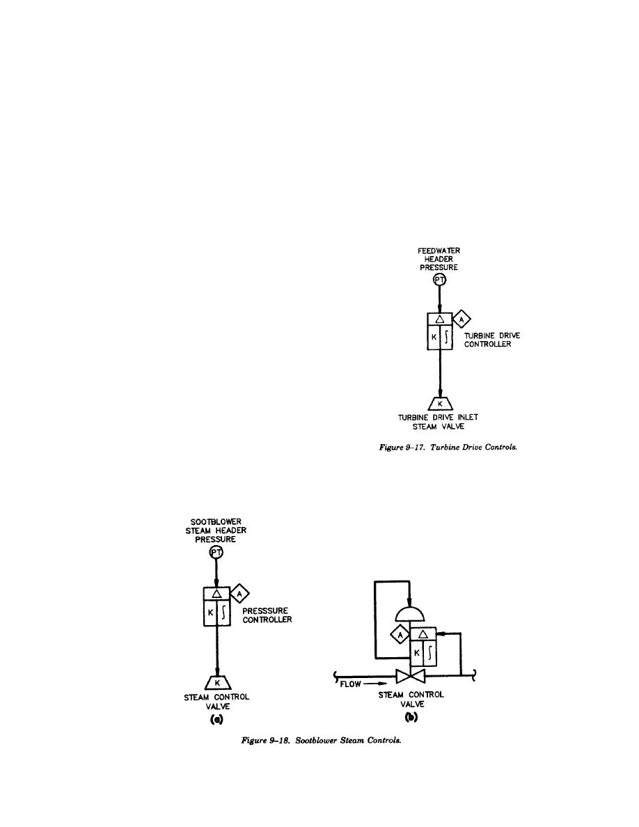
(1) Turbine drives. The boiler feed pump tur-
(4) Deaerator. The DA steam controls are a
bine drive is controlled by feedwater header pres-
pressure control system to maintain DA pressure.
sure. The steam control valve on the turbine drive
A single element loop with feedback as shown in
inlet is controlled by a pressure transmitter on the
figure 9-20 is adequate for controlling DA pres-
feedwater header acting through a controller as
sure.
(5) Feedwater heater. The feedwater heater
shown in figure 9-17. The setpoint pressure will be
lower than the normal operating feedwater pressure
controls as shown in figure 9-21 are used to protect
to prevent turbine drive operation during normal
the economizer against acid condensation. The
operating conditions.
economizer outlet gas temperature and economizer
(2) Sootblowers. Sootblower steam controls
inlet feedwater temperature are averaged. The
are normally a pressure control system to maintain
average is used to control the feedwater
the proper steam pressure at the sootblower inlet.
temperature by regulating the steam input to the
If remote indication of the sootblower steam header
feedwater heater.
pressure is desired a transmitter and controller will
be used as shown in figure 9-18(a). If remote
indication is not required a pressure controller
mounted on the control valve can be used as shown
in figure 9-18(b).
(3) Steam coil air heater. The steam coil air
heater controls are based on maintaining the flue
gas leaving the air heater above the acid dew point
temperature. This is accomplished by using an
average cold end temperature control system as
shown in figure 9-19. Air heater average inlet air
temperature and average gas outlet temperature are
calculated. These two signals are averaged to arrive
at the average cold end temperature, which is used
to control the steam coil control valve. Also, the
control system should include an interlock that
opens the steam coil control valve 100 percent
when the ambient air is below a set temperature,
usually 35 degrees F.
9-17


 Previous Page
