UFC 3-440-01
14 June 2002
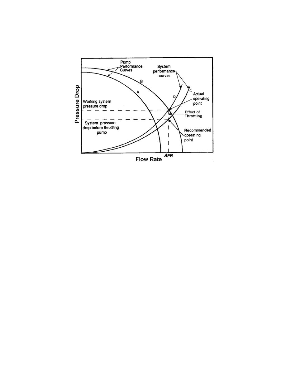
Figure 4-10. Typical Pump and System
Operation Curves
4.4.2.2.1
Component Connections. Major system components, such as the
collector banks, storage tank, heat exchanger, and circulation pumps, should be able to
be valved off and removed for cleaning, repair, or replacement. Installing valves on
both sides of the component usually provides this feature.
4.4.2.2.2
Roof Penetrations. Roof penetrations for the array supply and return
piping and sensor wiring conduit should be designed carefully to prevent leaking and to
account for movement due to thermal expansion. Standard penetration schemes (such
as those used for plumbing system vents) can fail because of the increased
temperature extremes to which solar system piping is subjected.
4-5
CONTROL SUB-SYSTEM. There are four areas concerning the control sub-
system that needs to be addressed during the final design stage. These include
specification of a control unit, location of control sensors, the location of local
monitoring equipment, and measurement of thermal energy delivered by the system.
4-5.1
Differential Temperature Control Unit (DTC). The proper specification of
the differential temperature control unit is important to ensure reliable system
performance. Because the cost of a simple solar system controller is small relative to
the total system cost, a high quality, commercially available unit is recommended. The
controller should include solid-state design with an integral transformer. The designer
should also ensure that the switching relay or other solid state output device is capable
of handling the starting current imposed by the system pump(s). The control unit
should allow the on and off set-points to be variable, and should allow the
instantaneous temperatures of the collector and storage tank to be displayed by the
system operator or maintenance personnel. Faulty sensors are a common cause of
system failure, so it is desirable to choose a control unit that will diagnose and flag open
4-22


 Previous Page
