UFC 3-460-03
21 JANUARY 2003
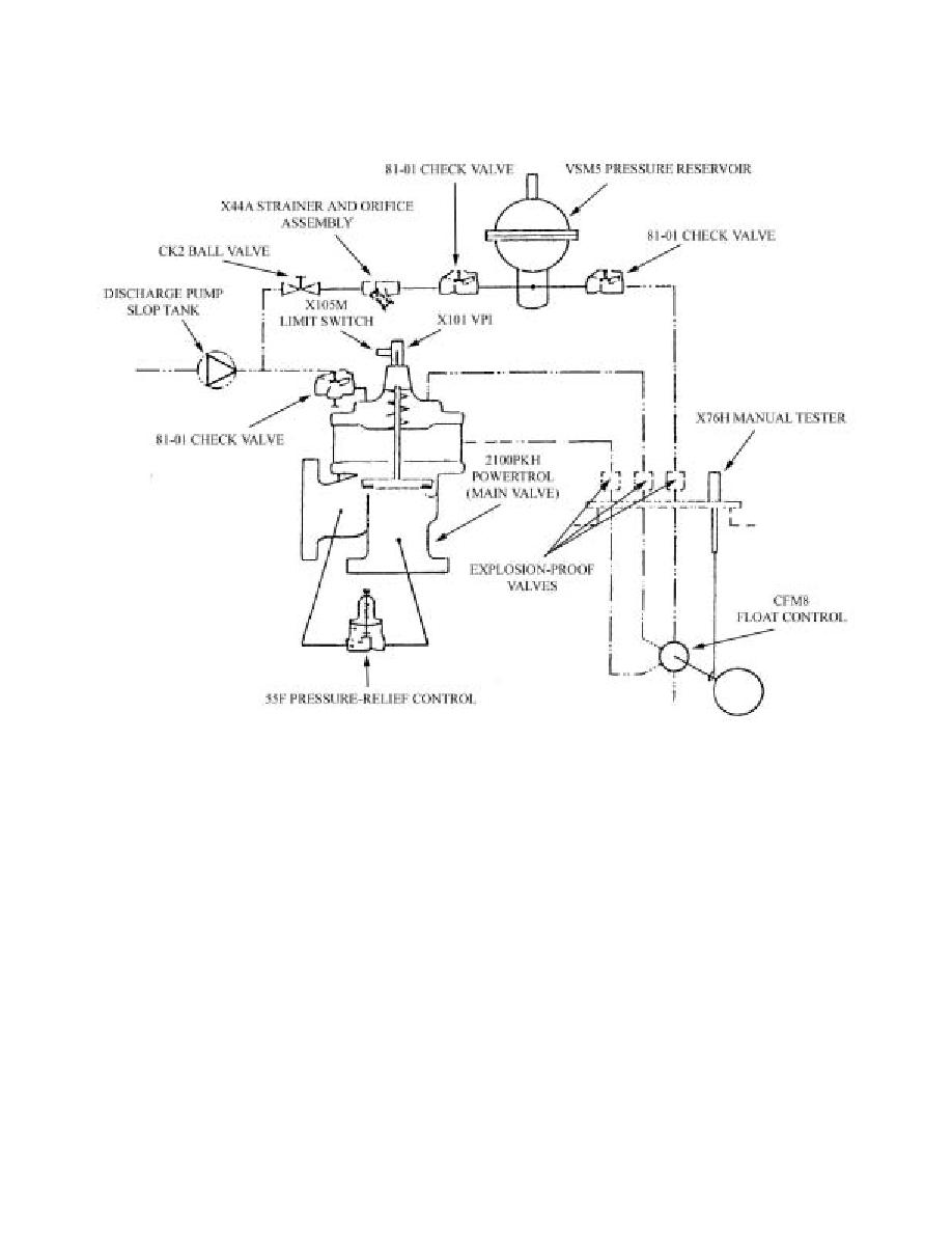
Figure 6.10. OV (2129AF).
6.5.5. Thermal Relief. Because the 2129AF would be held shut when the tank is 80% full, there is a
means of relieving excessive pressure in the product recovery piping system. This is done by a CRL
piped into the inlet and outlet of the 2129AF main valve body. When the product recovery piping
system pressure reaches 200 psi, the pressure relief control opens and allows the excess pressure to
bleed around the overfill valve.
6.5.6. Pump Control Room. The pump control room contains the PCP and the motor control center
(MCC).
6.5.7. PCP. The PCP is the heart of the Type III system. It contains the two microprocessors,
graphic display annunciator panel and alarms, pressure/flow recorders, and operator controls.
6.5.7.1. Graphic Display. The graphic display shows the layout of the system in a line drawing
format. Green lines show receiving and hydrant loop return lines and yellow lines show pump
suction from the storage tank discharge lines to the pump inlets. Yellow lines also show water
draw-off lines from the F/Ss and pressure relief valves which go to the product recovery tank.
Blue lines are the pump discharge and hydrant loop, including the BPCV, PCV, and the D/FV.
Green and red lights show which valves are open and or closed and which pumps are operating. A
digital readout shows the fuel level in each tank in tenths of an inch. If fuel is being received, a
digital counter shows the amount of fuel received.
65


 Previous Page
