UFC 3-460-03
21 JANUARY 2003
fueling point. In the automatic idle mode the loop is under constant pressure (75 psi) and protected
from thermal expansion by relieving excess pressure to the operating storage tank. A drop in system
pressure to 60 psi causes the lead pump to be energized. Because the hydrant loop is very long, high-
point vents and low-point drains are provided throughout. The number and location of hydrant
outlets are based on the types of aircraft and mission fueling requirements. The hydrant pit is molded
fiberglass with a counterbalanced aluminum cover. It opens to 90 degrees and requires
133.4 newtons (30 pounds force) to open it and 222 newtons (50 pounds force) to close. Most new
covers are designed to be watertight. Pipe penetrations in the pit are sealed by Buna-N boots clamped
to the pipe. The hydrant riser is either 101 millimeters for 2271-liter-per-minute (600-gallon-per-
minute) flows or 152 millimeters for 4542.4-liter-per-minute (1200-gallon-per-minute) flows. An
appropriately sized ball valve is installed before the HCV.
6.4.11. HCV (362AF-8):
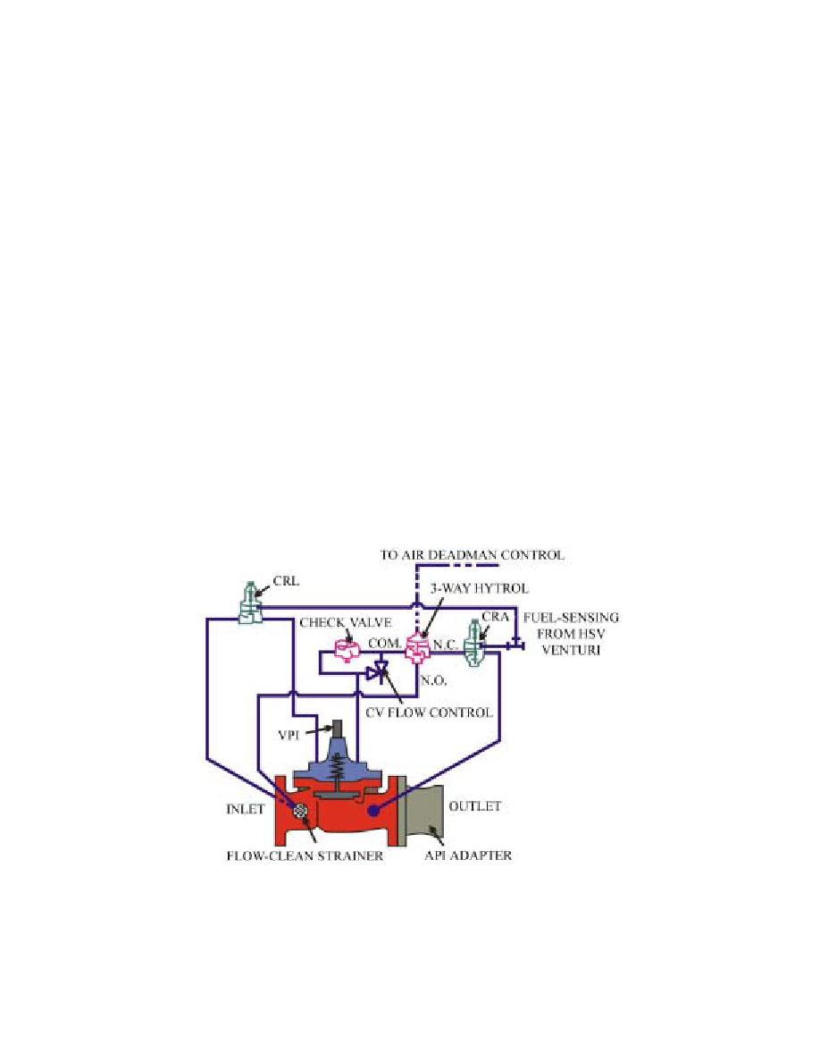
6.4.11.1. The HCV (Figure 6.6) provides a constant nozzle pressure and relieves excess pressure.
An air-sensing line is connected from the HSV to the HCV three-way hytrol. When the HSV's
pneumatic deadman is depressed, air is supplied to the three-way hytrol, allowing the valve to
open. A fuel-sensing line is connected from the HSV venturi to the pressure-reducing control
(CRA) and the CRL on the 362AF-8. The venturi is calibrated to provide the same pressure as the
actual nozzle pressure at the skin of the aircraft. The CRA maintains 45 psi at the nozzle. The
HCV is designed to close rapidly when the nozzle pressure exceeds the 50-psi setting of the CRL.
It reopens when the pressure drops below this set point.
Figure 6.6. HCV (362AF-8).
6.4.11.2. Valve Setting. Typical settings for the CRA is 45 psi and CRL is 50 psi. Set these
controls by turning the adjusting stem clockwise to increase pressure and counterclockwise to
decrease pressure. After establishing fuel flow through the HSV to a refueling truck, bottom the
CRL on the 362AF-8. Adjust the CRA to 50 psi and turn the CRL adjusting stem
counterclockwise until the valve begins to close. Next, turn the CRA counterclockwise until the
nozzle pressure drops to 45 psi. The main valve opening speed is adjusted by turning the CV flow-
60


 Previous Page
