UFC 3-460-03
21 JANUARY 2003
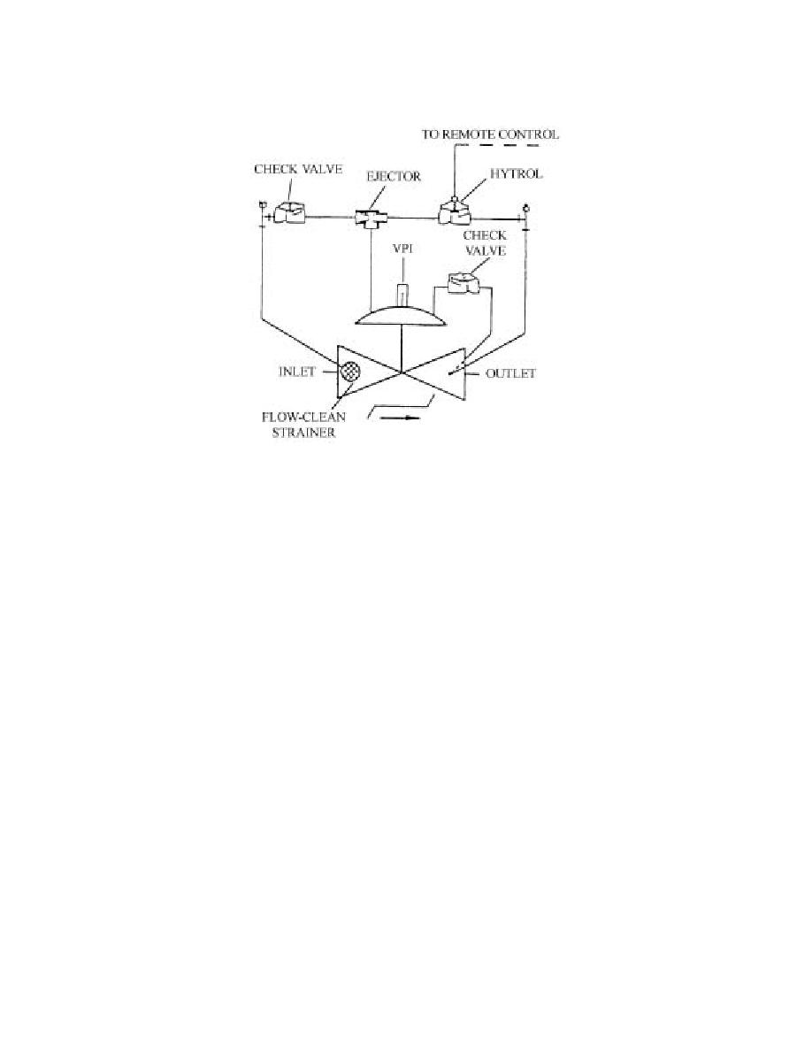
Figure 6.2. HLSO Valve (413AF-5A).
6.3.2.3. High-High-Level Alarm (HHLA). The float assembly for this alarm is above the HLSO
valve float assembly and below the tank overflow vents. This alarm indicates that both the HLA
and the HLSO have been ineffective and the tank is about to overflow. It actuates a flashing
HHLA window on the PCP and a resonating horn. After acknowledgment, the horn stops and the
window stops flashing, but stays lit until the level drops below the HHLA.
6.3.2.4. Low-Level Alarm (LLA). Each operating storage tank is equipped with a low-level float
assembly at the bottom of the tank. The LLA and shut-off switch controller will cause a visual
alarm at the annunciator panel and resonating alarm, and shuts down all fueling pumps when the
fuel level drops to the predetermined level.
6.3.2.5. HLA Test Procedure. Manually test the HLA and HHLA by isolating the float assembly
from the tank and filling it slowly with fuel until the HLA sounds the vibrating horn and the
HHLA sounds the resonating horn. Both alarms will activate visual alarms on the annunciator
panel. An audible alarm should also sound outside the building for both control systems. After
testing, drain the fuel from the float assembly through the drain valve before opening the tank
isolation valves. This prevents fuel from draining into the tank above the floating pan.
6.3.2.6. LLA Test Procedure. Test the LLA by isolating the float assembly from the tank and
draining it until the resonating horn and the visual alarms are activated at the annunciator panel
and outside the building. After testing, close the drain line and reopen the tank isolation valves.
6.3.2.7. Automatic Tank Gauges (ATG). All tanks handling jet fuel will have ATG installed. This
system is used for transfer and inventory control. The Petrol Ram division of the Air Force
Petroleum Office (AFPET), Fort Belvoir, Virginia, is the DoD agent for acquiring these systems.
Because of unique software requirements and the need to interface with the DoD Fuels Accounting
System (FAS), alternate systems must not be installed.
6.3.2.8. Outlet Valves. Each tank has a manual DBB valve at the tank outlet. In the Type III
system, one outlet valve must be open and one closed for the system to operate. The tanks are
equipped with a limit switch that illuminates a light on the system display panel that shows if the
56


 Previous Page
