UFC 3-460-03
21 JANUARY 2003
5.16.3.1.5. If the pressure is more than 5 psi, slowly turn the adjusting screw counterclockwise
until the pressure drops to 5 psi.
5.16.3.1.6. If the pressure is less than 5 psi, turn the adjusting screw clockwise to raise the CRL
setting, then repressurize the system and adjust the CV flow control closing speed to provide a
smooth, pulsation-free operation.
5.16.3.1.7. Check the setting by starting and stopping the pump and checking the system
pressure.
5.16.3.2. High-Pressure CRL Setting:
5.16.3.2.1. Set up the system to dispense fuel through a hose cart to a truck.
5.16.3.2.2. Bottom the adjusting screw on the 51AF-4 high-pressure CRL.
5.16.3.2.3. Bottom the adjusting screw on the 90AF-8 CRL.
5.16.3.2.4. Place the magnet on the KISS switch to start the deep-well turbine pump.
5.16.3.2.5. Slowly turn the 90AF-8 CRD clockwise until the pressure gauge in the pit reads
5 psi above the normal setting of the 90AF-8 CRL.
5.16.3.2.6.
Slowly turn the adjusting screw on the 51AF-4 high-pressure CRL
counterclockwise until the valve starts to open.
5.16.3.2.7. Stop and start the deep-well pump to recheck the setting.
5.16.3.2.8. Adjust the 90AF-8 CRD to 5 psi above NOP.
5.16.3.2.9. Adjust the 90AF-8 CRL counterclockwise until you get a 2- to 3-psi drop.
5.16.3.2.10. Adjust the 90AF-8 CRD to NOP.
5.16.3.2.11. Restore the system to original condition.
5.16.4. 358AF Hydrant Adapter. To conduct rapid defueling operations, the float assembly in the
352AF valve was removed. A 3.1-millimeter angle valve was installed in the tapped hole in the body
of the hydrant adapter to manually bleed off vapor and air. To prevent air from entering the system
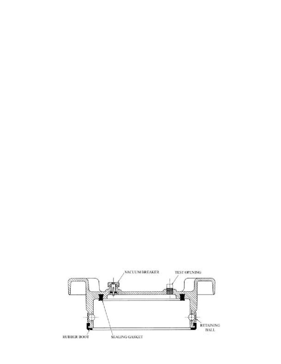
when the hydrant is not in use, an X73 aluminum blanking cap, shown in Figure 5.14, has replaced
the rubber dust cover. A manual vacuum breaker was installed in the cap to dissipate any vacuum in
the adapter so the cap can be removed. This modified valve is called the 358AF hydrant adapter.
Figure 5.14. X73 Aluminum Blanking Cap.
52


 Previous Page
