UFC 3-460-03
21 JANUARY 2003
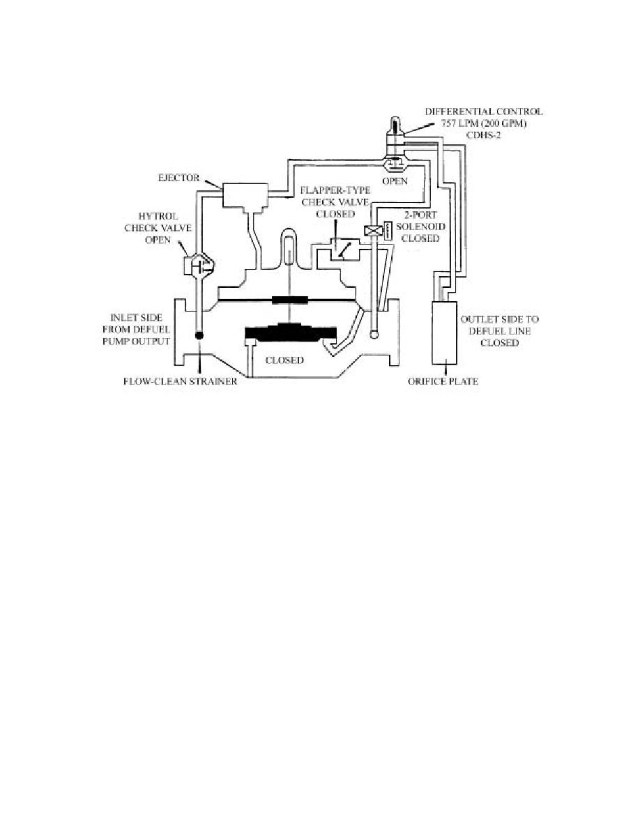
Figure 5.12. Combination Dual Rate-of-Flow Control Valve and Solenoid Valve (41AF-10).
5.16.2. Combination Dual Pressure Relief, Solenoid Shutoff and Check Valve (51AF-4):
5.16.2.1. General. The dual pressure relief valve (Figure 5.13) is installed in the modified hydrant
lateral control pit downstream of the refueling control valve between the hydrant lateral pipe line
and the defueling line (bypass piping around defuel pump, as shown in Figure 5.1). This relief
valve performs two functions: relieves excess pressure in the hydrant lateral piping caused by
quick-closing valves during the refueling operation; and maintains a minimum pressure of
5 psi on the hydrant lateral piping when the refueling pumps are not in operation. This valve also
has a CV flow control to slowly close the valve during rapid defueling operations.
50


 Previous Page
