UFC 3-460-03
21 JANUARY 2003
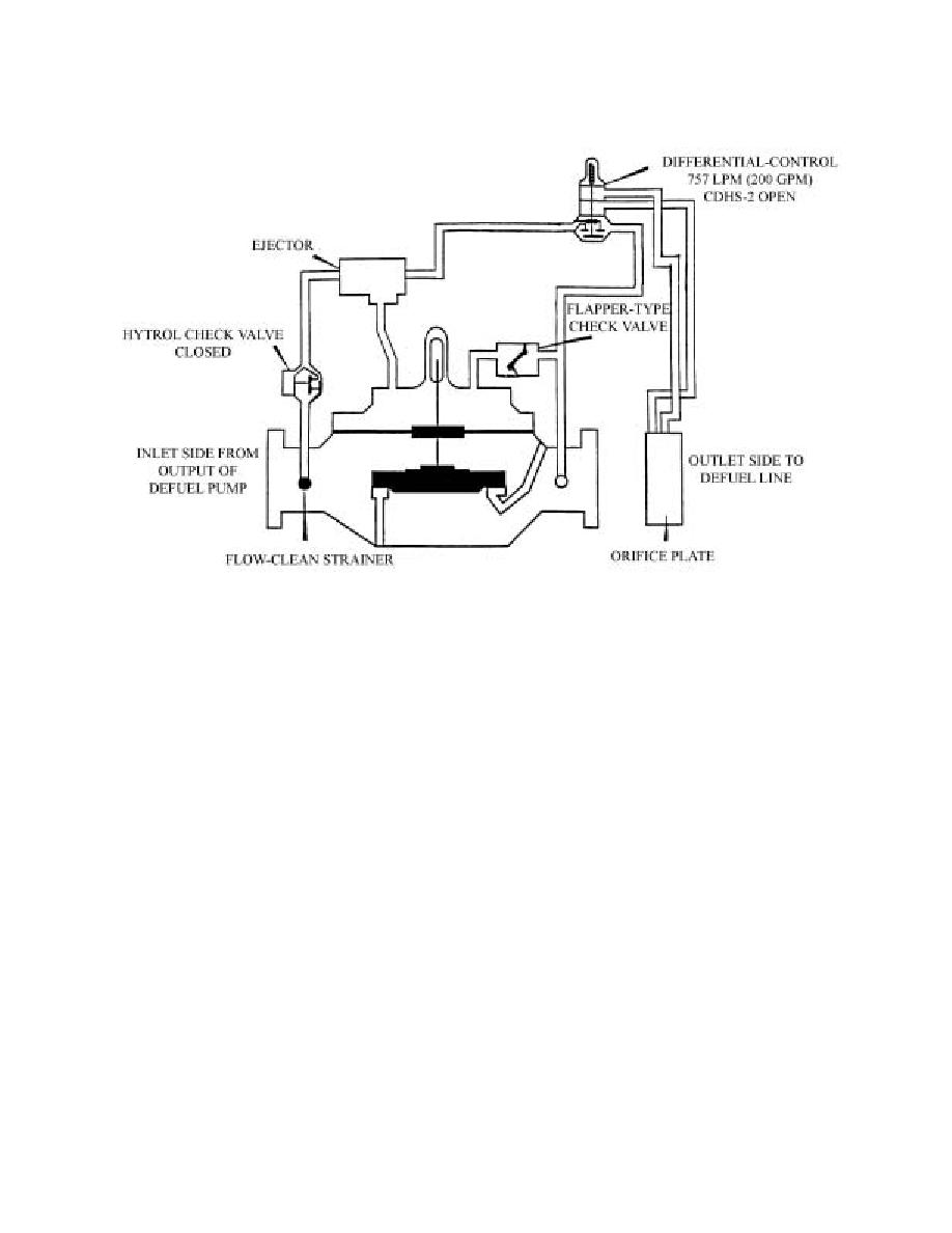
Figure 5.7. Dual Rate-of-Flow Control Valve (41AF).
5.10. Recommended Setting Procedure for Rate-of-Flow Control Valve (41AF).
5.10.1. With no pressure on the system, back off on the CDHS-2 and stop as soon as spring-tension
is lost.
5.10.2. Turn the adjusting screw clockwise two complete turns to get the lowest rate-of-flow setting
on the CDHS-2. NOTE: Never apply pressure to CDHS-2 if the adjusting screw has less than this
two-turn setting.
5.10.3. Set up the system to defuel through the 41AF.
5.10.4. Place the magnet on the defuel KISS switch.
5.10.5. Turn the CDHS-2 stem clockwise until you get a flow rate of 757 liters per minute
(200 gallons per minute).
5.10.6. Remove the magnet from the KISS switch.
5.10.7. Return the system to its original condition.
the aircraft into the designated defuel tank at the pumphouse. The defueling switch at the hydrant outlet
controls this pump. The self-priming centrifugal defueling pump (Figure 5.8) differs from a standard
centrifugal pump because a vane-type suction pump is mounted on the pump shaft. When the main
pump discharge pressure is below 10 psi, the priming pump is in the priming position (Figure 5.9). It
draws from the suction side of the pump and discharges at a point downstream of the check valve, so
priming the centrifugal pump. When the main pump discharge pressure reaches 10 psi, the priming
pump moves into the neutral position.
46


 Previous Page
