UFC 3-460-03
21 JANUARY 2003
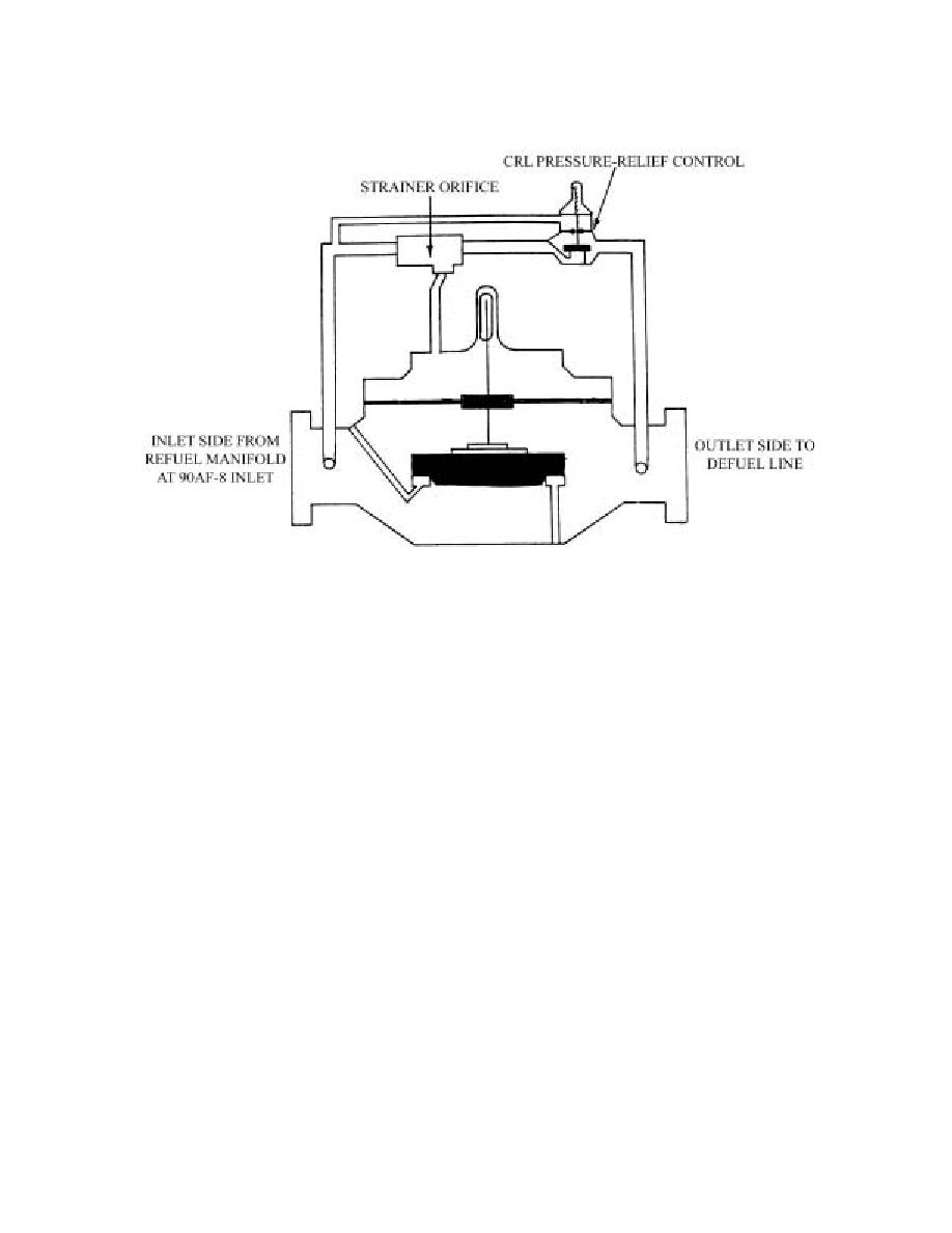
Figure 5.5. Pressure Relief Valve (50AF-2).
5.7.2. Pressure Setting. The 50AF-2 should be set at 10 psi above normal inlet pressure to the
90AF-8 (typical settings are in the range of 110 to 125 psi).
5.7.3. Recommended Setting Procedure for the Refueling Control (90AF-8) and Pressure Relief
Valve (50AF-2).
5.7.3.1. Set up system to refuel through the 90AF-8 valve.
5.7.3.2. Ensure a gauge is installed at the farthest hydrant outlet.
5.7.3.3. Be sure the CDHS-3 is in the cocked position.
5.7.3.4. Bottom both CRLs (90AF-8 and 50AF-2).
5.7.3.5. Energize the system and establish a smooth flow.
5.7.3.6. Adjust the 90AF-8 CRD until the gauge at the farthest outlet reads 105 psi.
5.7.3.7. Back off on the 90AF-8 CRL until the gauge needle dips (2 to 3 psi is acceptable).
5.7.3.8. Adjust the 90AF-8 CRD until the gauge at the outlet reads 100 psi (note the 90AF-8 inlet
pressure).
5.7.3.9. De-energize system.
5.7.3.10. Close a manual valve downstream of the 90AF-8 and shut off the 90AF-8 solenoid
switch.
5.7.3.11. Energize the system.
5.7.3.12. Back off on 50AF-2 CRL set screw until the valve starts to open and the inlet pressure is
10 psi above the normal inlet pressure recorded in paragraph 5.7.3.8 above.
5.7.3.13. De-energize the system.
5.7.3.14. Open the manual valve and turn on the solenoid switch (paragraph 5.7.3.10).
44


 Previous Page
