UFC 3-460-03
21 JANUARY 2003
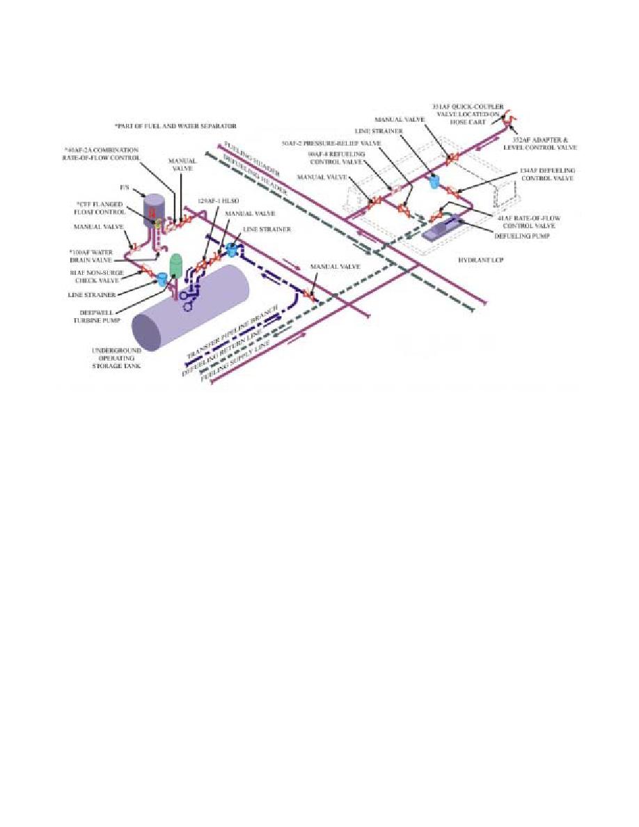
Figure 5.1. Pritchard, Type II Hydrant System.
5.1.2. Defueling. When it is necessary to evacuate a hose cart or defuel an aircraft, the operator
to open and the defuel pump to be energized. Fuel is then drawn through the defuel pump and forced
through the 41AF rate-of-flow control valve into the defuel line at a rate of 757 liters per minute
(200 gallons per minute). Fuel flows to the operating tank designated to receive the product.
5.2. Deep-Well (Vertical) Turbine Pump. Pump design is the same for both Types I and II hydrant
fueling systems. See Chapter 3 for a description and Chapter 10 for maintenance frequencies.
5.3. Nonsurge/Check Valve. The 81AF has been converted to the 81AF-8 nonsurge/check valve
(Figure 5.2). This modification involves replacing the swing check valves with hytrol check valves.
The speed control setting is the same as described for the Type I Panero system (paragraph 4.4.2.2.).
40


 Previous Page
