UFC 3 -520-01
June 10, 2002
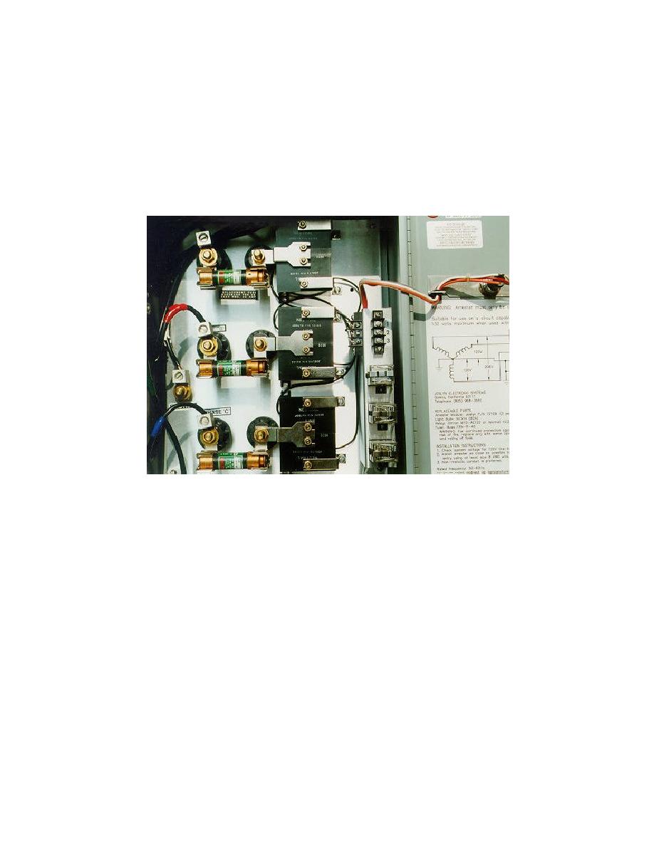
fire after an MOV degrades to the point that it continuously conducts current. Newer
designs often individually fuse each MOV. In addition, a fuse might be installed for each
separate mode of protection. Figure D -3 shows an example of fusing for each module.
If the selected surge protector has this type of fuse arrangement, verify with the
manufacturer the overcurrent characteristics of the fuse when exposed to transient
surge currents.
Figure D -3. Example of Internally Fused Surge Protector
D-2.8
Installation Capability.
D-2.8.1 Surge protectors covered by this manual should normally be of the parallel
type. The surge protector size and installation method are important evaluation
considerations. If the surge protector enclosure is over-sized, it might not fit near the
required location, thereby causing the lead length of the connecting conductors to be
excessive, which increases the let-through voltage.
D-2.8.2 Figure D-4 shows an example of an unacceptable design; this example has
two problems. First, the e nclosure size ensures that the connection leads will be long,
which increases the let-through voltage. Second , the large enclosure might not fit
where it should be installed-- near the equipment to be protected-- which again ensures
excessive lead length.
D-7


 Previous Page
