UFC 3-535-01
17 November 2005
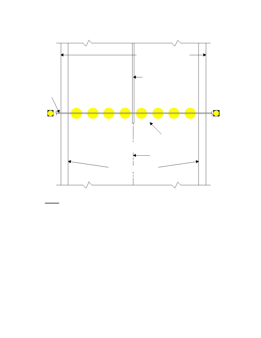
Figure 9-9. Arresting Gear Marker (AGM) Configuration
60M (200FT) WIDE RUNWAY
RUNWAY
CENTERLINE
MARKING
PENDANT
AGM
AGM
REFERENCE ONLY
RUNWAY
CENTERLINE
RUNWAY EDGE STRIPES
NOTES:
INSTALL AGM IN LINE WITH RDM.
IF AN RDM IS WITHIN 6M (20FT) OF AN AGM, THEN MOVE
THE RDM EVEN WITH THE AGM AND INSTALL IT 1.5M (5FT)
OUTBOARD OF THE AGM.
9-7.3.4
Photometrics
The average sign luminance, as determined in accordance with FAA AC 150/5345-44,
must be as follows for all intensity steps: Yellow legend, 16 to 30 foot-lamberts.
9-7.4
Power and Control
See paragraph 9-6.4. The AGM should be powered from the same source and circuit as
the RDM.
146


 Previous Page
