UFC 3-535-01
17 November 2005
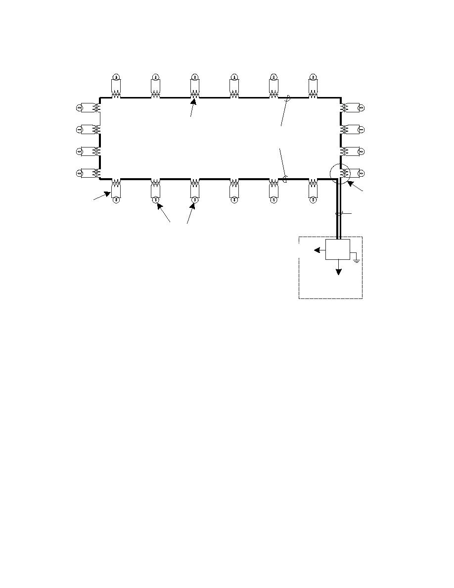
Figure 15-2. Typical AGL Series Lighting Circuit
ISOLATION
PRIMARY CIRCUIT
(5KV Cable, #8 or #6 AWG
in Conduit or direct buried)
LIGHT BASE
SECONDARY
CIRCUIT
HOME RUN
(from first fixture)
LIGHT FIXTURE
(OR SIGN)
NOTE: 120/240V elements may
REMOTE
CCR
be connected with Power Adaptor.
CONTROL
POWER
SUPPLY
VAULT
15-1.3
Parallel circuits are briefly discussed as these may be used to serve
facilities such as wind cones, PAPI, REIL, and others. This may be directly from a
power source, or via power adapter from a series lighting circuit.
15-2
POWER
Upstream power for the CCR feeding the AGL may be from a variety of sources.
Equipment vaults for AGL may be fed from a variety of sources, and in many cases
have emergency standby generator power with automatic transfer in case of outages.
Older systems typically feed the CCR at 2400V, while newer installations feed vault
CCRs at 480V or 240V (used for some smaller installations). The upstream power
distribution feeding the CCR is not covered in this section.
15-3
CONTROL AND MONITORING SYSTEMS
Traditional control/monitoring systems, both military and commercial, are relay systems.
L-821 relay panels are very reliable and are suitable for nearly all military airfields.
Typically, cables required for these types of systems are multi-pair (50 or more pairs)
cables to connect the airfield lighting vault on the airfield with the air traffic control tower.
On many air bases, the distance between the two facilities is great, resulting in a costly
cable installation with the cable vulnerable to possible damage or failure of one or more
pairs in the cable. In addition, these communications cables require separate duct
systems to eliminate interference from the power cables. The traditional relay panel and
multi-conductor control cable can also be simplified by using a multiplexer, which
248


 Previous Page
