UFC 3-560-01
6 December 2006
Including change 1, 7 December 2006
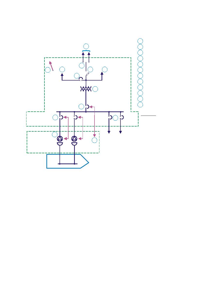
Figure 13-14. Preferred Ship-to-Shore Circuit Arrangement
1
To shore medium-voltage dist. system
1
2
Primary selector switch
3
Fused primary disconnect switch
4
5
Main CB with CS & ET pushbutton
2
10
11
3
12
6
Feeder CB with CS & LR
7
7
Feeder CB with CS only
8
Pier receptacle & plug with remote CB control
Substation
9
ET pushbutton
4
10
To vault power
11
To meters & control power
Vault Pier
12
Vault alarm circuits
5
Ship Power
Power
Acronyms:
6
7
CB - Circuit breaker
CS - Control switch
ET - Emergency trip
LR - Local remote control
8
9
Pier Outlet
Assembly
Ship
13-3.2.1 General Electrical System Safety. The maintenance and operation safety
aspects of the high-voltage distribution system, substations, vaults, and low-voltage
cables in duct lines is covered in previous sections.
13-3.2.2 Specific Shore-to-Ship Electrical System Safety. This section covers
connection of portable power cables to shore electrical outlet assemblies and ship
electrical buses. Connection is a divided responsibility as shown in Table 13-1. Follow
the Standard Operating Procedure (SOP) established by the Shore ES. An example of
the SOP for a typical vault substation arrangement to ensure that energizing the ship is
accomplished safely is shown in Figure 13-15.
13-12


 Previous Page
