TM 5-811-7
APPENDIX F
RECTIFIER CURRENT INTERFERENCE*
F-1. This appendix is taken from an unpublished document by T.F. Lewicki of the U.S. Air Force Civil
Engineering Center, Tyndall Air Force Base, FL. It is used in the Air Force Corrosion Reports as an
internal document.
F-2. Cathodic interference.
a.
Method of detecting cathodic interference.
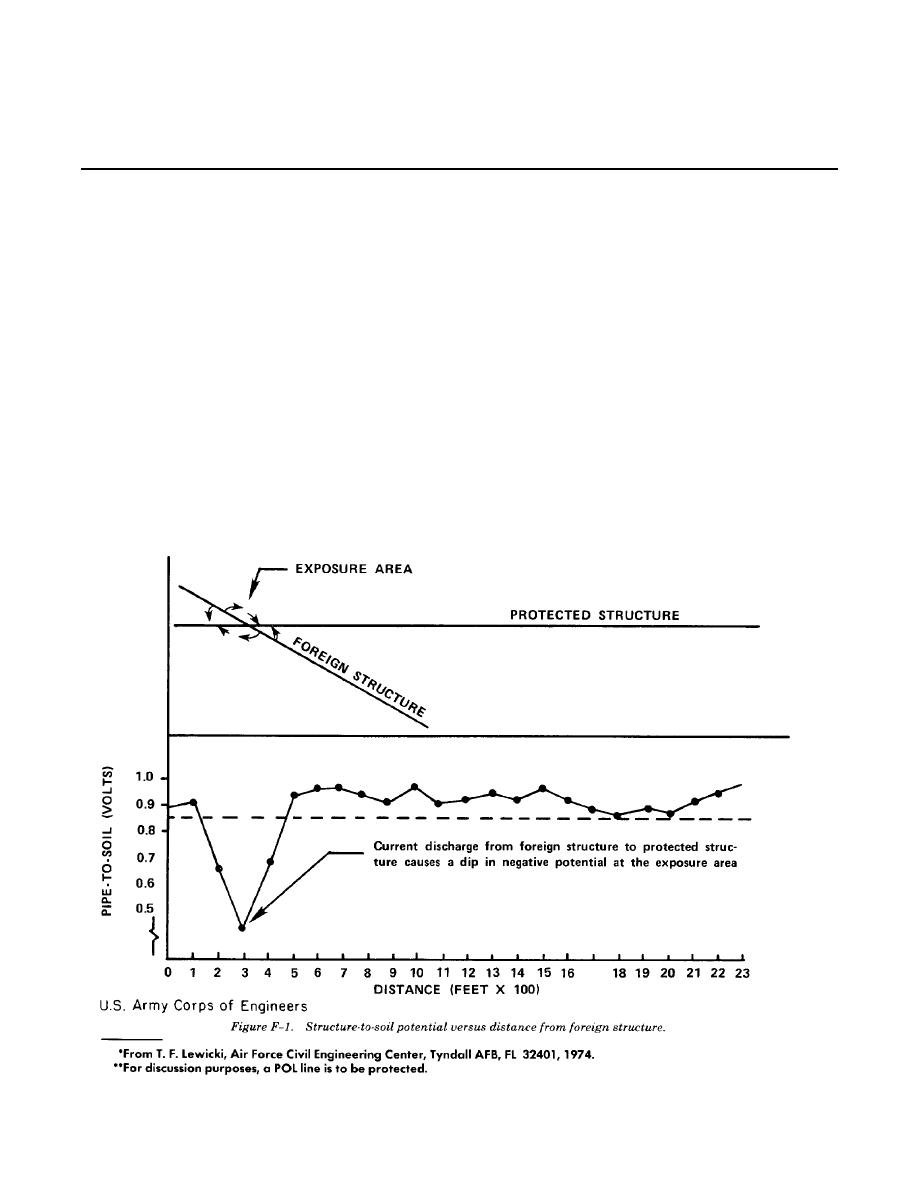
(1) Cathodic interference may be detected by conducting structure-to-soil potential surveys on all
foreign underground structures in the vicinity of the impressed current systems or the structure being
protected. The results are usually plotted as a curve as shown in figure F-1.** To save time, a shortcut
method of detecting cathodic interference may be used. Base maps showing the locations of the proposed
rectifier ground beds, the protected POL system, and all foreign structures should be obtained and studied.
A foreign structure is considered to be a structure which is not part of, or metallically connnected to, the
protected structure. Foreign underground structures that come close to (400 to 1000 feet) the ground bed
and cross or come close to the protected structure at some remote location (greater than 1000 feet from the
ground bed) are prime suspects for cathodic interference. All other suspects should not be ruled out, but the
structures that fit into the category described in the previous sentence will be the most likely structures to
have interference problems. The point at which the foreign structure crosses or comes closest to the protected
structure is the most likely point of cathodic interference or current discharge, commonly referred to as
maximum exposure area. An exception to this would be a case where the foreign structure was well coated.
The holiday in the coating closest to the crossing could be a considerable distance from the crossing.
F-1


 Previous Page
