MIL-HDBK-1005/9A
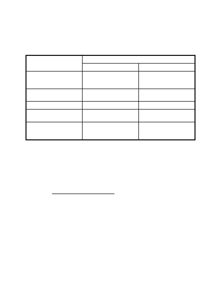
Table 14
API Separator Design Criteria
Design Parameter
Design Flow Rate
<185 gpm (11.7 L/s)
>185 gpm (11.7 L/s)
1
2
Maximum Surface
1,000 to 2,000
1,000 (11.3)
Loading, gpd/ft2
(11.3 to 22.6)
(L/s-m2)
Length:Width
4:1
4:1
(minimum)
Depth:Width
1:1 (maximum)
0.3:1 to 0.5:1
3
Maximum Depth, ft
3 (0.9)
5 (1.5)
(m)
Maximum Horizontal
2 (0.6)
2 (.06)
Velocity, fpm
(m/min)
1
Based on maximum 24-hour flow with one tank out of service.
2
Use lower value if separator is only form of treatment. Use
higher value of separator is a pretreatment or intermediate
component of a multi-unit treatment system or if effluent
quality complies with POTW discharge regulations.
3
Increase depth to provide oil and sludge storage volume as
required.
3.10.4.1 Parallel Plate Separator. Use the wastewater
characteristics developed in accordance with Section 3. Refer
to paragraphs 3.7.2 and 2.7.4 to design separator for removal of
free oil and, if required, suspended solids. Locate units above
ground or partially buried. Protect buried units against
flooding from surface runoff by locating a minimum of 8 inches
(203 mm) above grade. Consider the following during design:
a) Tanks should be fabricated from carbon steel and
coated inside and outside with coal tar epoxy. Preferred
construction materials for plate packs are a frame of Type 304
stainless steel with individual plates of fiberglass. Refer to
142


 Previous Page
