UFC 3-440-01
14 June 2002
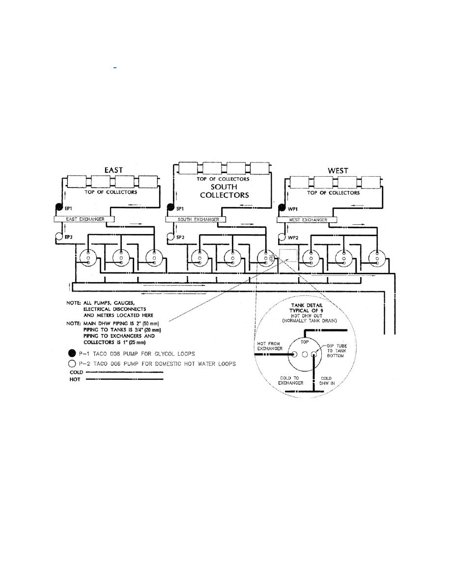
listed on Figure G-2 as P-1 and P-2. For each array, pump P-1 circulates a water-glycol
solution through the panels and heat exchanger. Pump P-2 circulates domestic water
from the building through the heat exchanger and storage tanks. Figure G-5 illustrates
the connection of the solar supply and return lines to the existing recirculating domestic
water system. The storage tanks, heat exchangers, and pumps are located in the
housing behind the second row of collectors. The backside of the housing is removable
to allow access to the equipment as illustrated in Figure G-6.
Figure G-2. Solar Hot Water System Piping Diagram
c. System Controls. The system is controlled through the use of a differential
temperature controller. The system pumps are switched on when the temperature of
the collectors is greater than the temperature in the storage tanks. The system uses
two 10K ohm thermistors for the differential temperature control. One is located at the
outlet pipe of the glycol loop on the western most collector, while the other is located on
the incoming cold water line to the system. The wiring diagram for the system is
illustrated in Figure G-7. The photo of the system controller can be seen in Figure G-8.
G-3


 Previous Page
