TM 5 - 8 0 5 - 4 / A F J M A N 3 2 - 1 0 9 0
Table 5-5. Insertion Loss for Sound Transmission Through a
open windows in the near and far walls would
Growth of Medium-Dense Woods.
probably be acceptable, provided the interior
rooms are large. The building may qualify as a
Octave
Insertion
compound barrier.
Loss,
(8) Caution. A large flat reflecting surface,
dB per
Band,
such as the barrier wall, may reflect more sound
HZ
100 ft. of Woods
in the opposite direction than there would have
been with no wall at all present. If there is no
31
0
special focusing effect, the wall may produce at
most only about 2 or 3 dB higher levels in the
63
1/2
direction of the reflected sound.
125
1
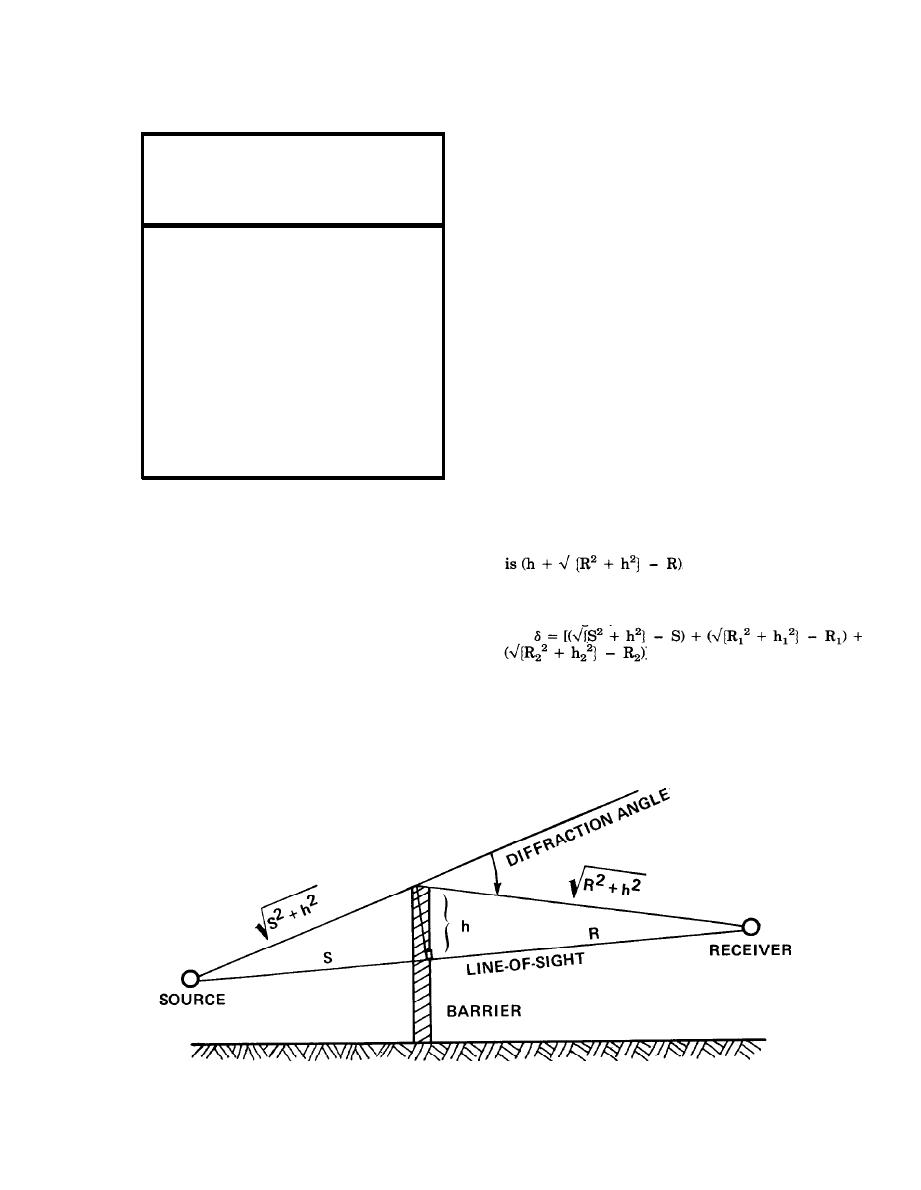
c. Unusual barrier geometries. Figure 5-8 illus-
trates three common situations that do not fall
250
1 1/2
into the simple geometry of figure 5-6. The proce-
500
2
dure suggested here is to estimate the path length
difference and use table 5-6 to obtain the insertion
1000
3
loss, even though this simplified approach has not
2000
4
been proven in field or model studies.
4000
4 1/2
(1) In-wall sound source. In part A of figure
5-8, the source could be a wall-mounted exhaust
8000
5
fan, an inlet to a ventilating fan, or a louvered
opening permitting air into (and noise out of) a
mechanical equipment room. The conventional
source distance S is zero and the slant distance
becomes h. Thus, the total path length difference
(2) Compound barrier. In part B of figure
5-10, the path length difference is calculated from
three triangles, as follows:
Part C of figure 5-9 is another form of compound
barrier and also requires the three-triangle calcu-
lation.
Figure 5-6. Parameters and Geometry of Outdoor Sound Barrier.
5-8


 Previous Page
