TM 5-805-4/AFJMAN 32-1090
PROCEDURE
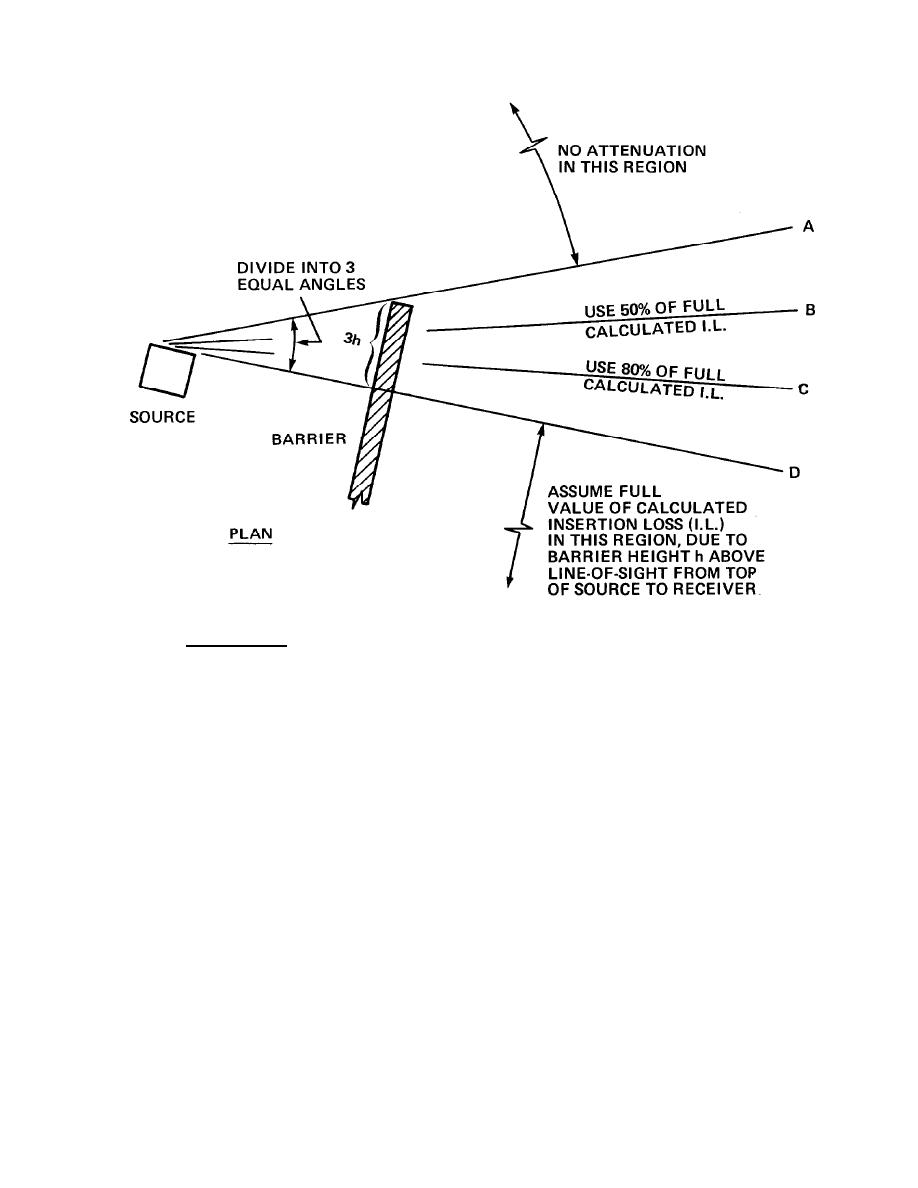
GIVEN: h IS HEIGHT OF BARRIER USED IN CALCULATION OF I.L.
STEPS:
1. MARK OFF HORIZONTAL DISTANCE 3h FROM EACH END
OF BARRIER (ONLY ONE END SHOWN IN ABOVE SKETCH)
2. DRAW LINES A AND D
3. DIVIDE ANGLE INTO 3 EQUAL PARTS
4. DRAW LINES B AND C
5. ASSIGN I.L. VALUES AS SHOWN; INTERPOLATE BETWEEN
-VALUES AS REQUIRED
Figure 5-9. Edge Effects at End of Barrier.
5-8. Source Directivity.
the penthouse mechanical room. The geometry for
this barrier produces a path length difference of
The analysis procedures of this chapter assume
0.23 feet. The insertion loss for the barrier is given
that the sound source radiates sound equally in
in column 4 of table 5-9. Column 5 gives the
all directions. In some cases this is not the case,
average outdoor SPL at the residence as a result of
that is more sound energy will be transmitted in
the barrier and the slightly increased distance to
one direction when compared to other directions.
the new location (Co1 5 = Co1 2 - Co1 3 - Co1 4).
This is referred to as the "Directivity" of the
Column 7 gives the new indoor SPLs which are
sound source. The directivity of a sound source
compared with the column 8 values of the NC-25
may be an inherent result of the design or may
be the result of the equipment installation very
curve. A noise excess of only 3 dB occurs in one
close to reflecting surfaces. In the example given
octave band. This would be considered a more
a b o v e the cooling tower directivity was not
nearly acceptable solution to the cooling tower
taken into account. In Location A, the SPLs at
noise problem.
5-12


 Previous Page
