TM 5-805-4/AFJMAN 32-1090
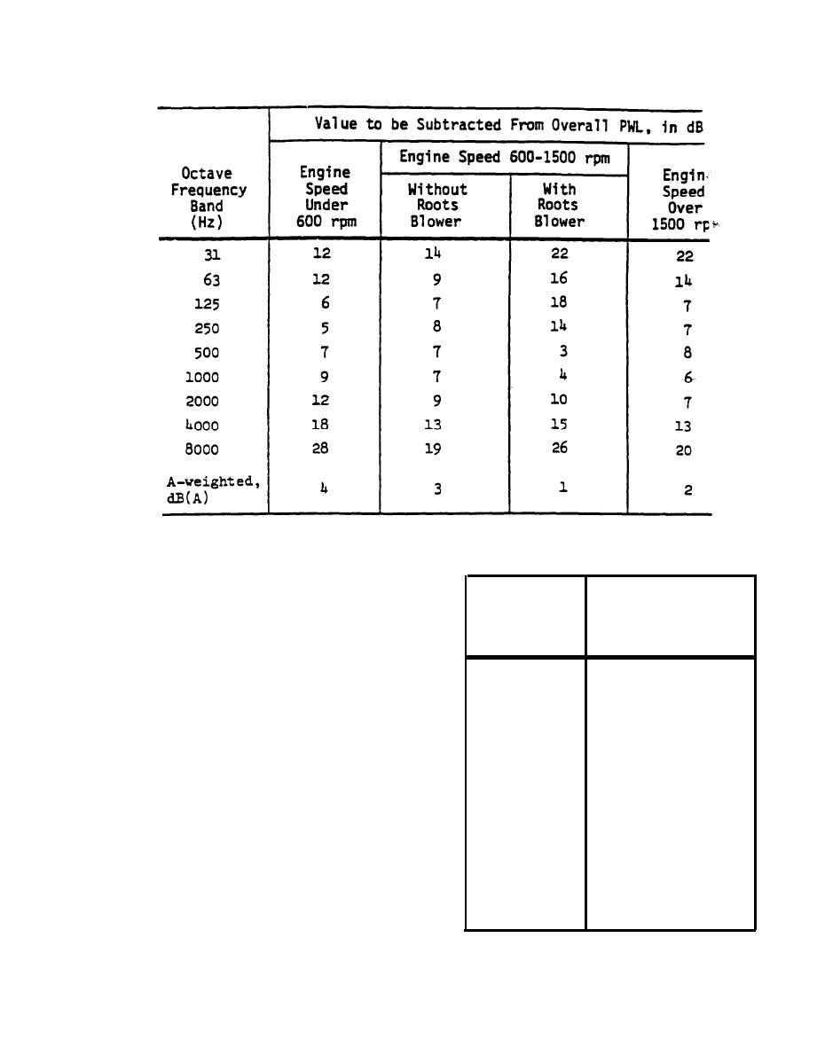
Table C-17. Frequency Adjustments (in dB) for Casing Noise of Reciprocating Engines.
the released exhaust gas of the engine. The tur-
Table C-18. Frequency Adjustments fin dB) for Turbocharger
Air Inlet Noise.
bine is a high-frequency sound source. Turbine
configuration and noise output can vary apprecia-
bly, but an approximation of the PWL, of the
Value to
Octave
turbocharger noise is given by equation C-7:
be Subtracted
Frequency
Lw = 94 + 5 log (rated hp) -L/6,
(eq C-7)
From Overall PWL
Band
(Hz)
(dB)
where Lw and "rated hp" are already defined and
L is the length, in ft., of a ducted inlet to the
4
31
turbocharger. For many large engines, the air
inlet may be ducted to the engine from a fresh air
11
63
supply or a location outside the room or building.
13
125
The term L/6, in dB, suggests that each 6 ft. of
inlet ductwork, whether or not lined with sound
13
250
absorption material, will provide about 1 dB of
12
500
reduction of the turbocharger noise radiated from
the open end of the duct. This is not an accurate
9
1000
figure for ductwork in general; it merely repre-
sents a simple token value for this estimate. The
8
2000
octave band values given in table C-18 are sub-
9
4000
tracted from the overall PWL of equation C-7 to
obtain the octave band PWLs of turbocharged inlet
17
8000
noise.
3
A-weighted,
ated from the unmuffled exhaust of an engine is
dB(A)
given by equation C-8:
Lw = 119 + 10 log (rated hp) - T - L/4
(eq C-8)
C-15


 Previous Page
