UFC 3-460-03
21 JANUARY 2003
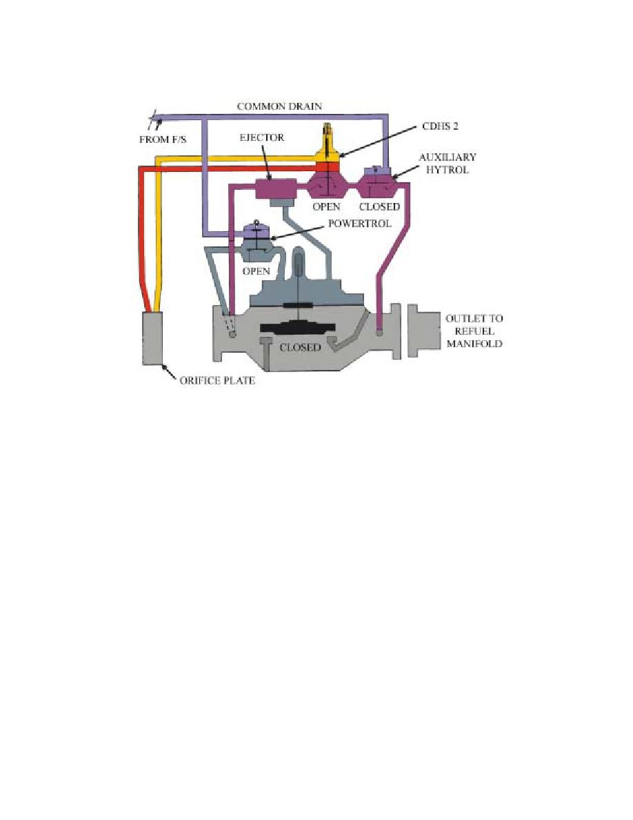
Figure 4.3. F/S Control Valve (40AF-2A).
4.4.3.2. Valve Settings. Set the rate-of-flow control to discharge at the vessel nameplate rating
(typically 2271 liters per minute [600 gallons per minute]) using the CDHS-2B. Turn the adjusting
stem clockwise to increase the flow rate and counterclockwise to decrease.
4.4.4. Meters. See Chapter 2 for description.
4.4.5. Three-Port, Two-Way, Refuel/Defuel Valve (302AF):
4.4.5.1. General. The 302AF is at the junction of the refuel and defuel line in the filter/meter pit.
The valve is unique in that it is a three-port automatic control valve. This allows fuel flow in two
directions through the same automatic valve: one direction for refueling and another for defueling.
When the KISS switch at the hydrant outlet is activated, the 302AF solenoid energizes and the
valve is ready to refuel. The valve automatically performs the following functions: reduces
pressure going to the hydrant outlet; relieves excess hydrant outlet pressure; shuts off in case of
excess flow (broken hose); and provides remote control of the valve. When the valve is de-
energized it provides a means for defueling aircraft by gravity flow.
4.4.5.2. Pressure Setting:
4.4.5.2.1. Set the pressure-reducing control (CRD) to maintain normal operating pressure
(NOP) at the furthest outlet. NOP is the lowest pressure capable of achieving maximum flow
rate and smooth operation. NOTE: The NOP for most Type I systems is 100 psi, measured at
the furthest outlet.
4.4.5.2.2. Set the unloading pressure-relief control (CRL) to open the defuel side at 10 psi
above NOP.
4.4.5.2.3. Set the loading CRL to close the refueling side at 5 psi above NOP.
4.4.5.2.4. Set the CDHS-3 according to the procedures in Attachment 3.
34


 Previous Page
