UFC 3 -520-01
June 10, 2002
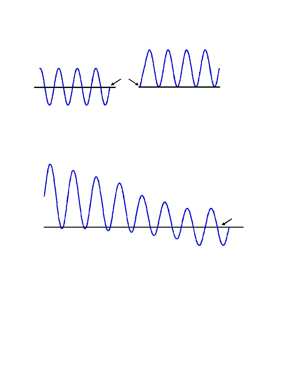
Figure 2-2. Completely Symmetric or Asymmetric Current
Completely Symmetric
Zero Axis
Completely Asymmetric
2-4.3.2 Figure 2-3 shows a typical short circuit waveform for a low voltage system.
The ratio of reactance to resistance exhibited by a system during a fault affects the
instantaneous magnitude and duration of the short circuit current peak and can affect a
circuit breaker's interrupting rating. For this reason, consider both the symmetrical and
asymmetrical short circuit current in a breaker rating evaluation.
Figure 2-3. Typical Asymmetrical Short C ircuit Behavior
Zero Axis
2-4.4
Short Circuit Calculations.
2-4.4.1 Electrical distribution systems must be designed to withstand the maximum
expected fault (short circuit) current until the short circuit current is cleared by a
protective device. This is a fundamental electrical requirement. NEC Article 110.9
(2002 Edition) requires that all protective devices intended to interrupt current at fault
levels must have an interrupting rating sufficient for the nominal circuit voltage and the
current that is availa ble at the line terminals of the equipment. For this reason, the
maximum available short circuit current must be determined for all locations throughout
the electrical system requiring overcurrent protection.
2-4.4.2 Calculate short circuit currents in s upport of the following equipment selection
activities:
Verification of interrupting rating of protective devices.
2-7


 Previous Page
