UFC 3 -520-01
June 10, 2002
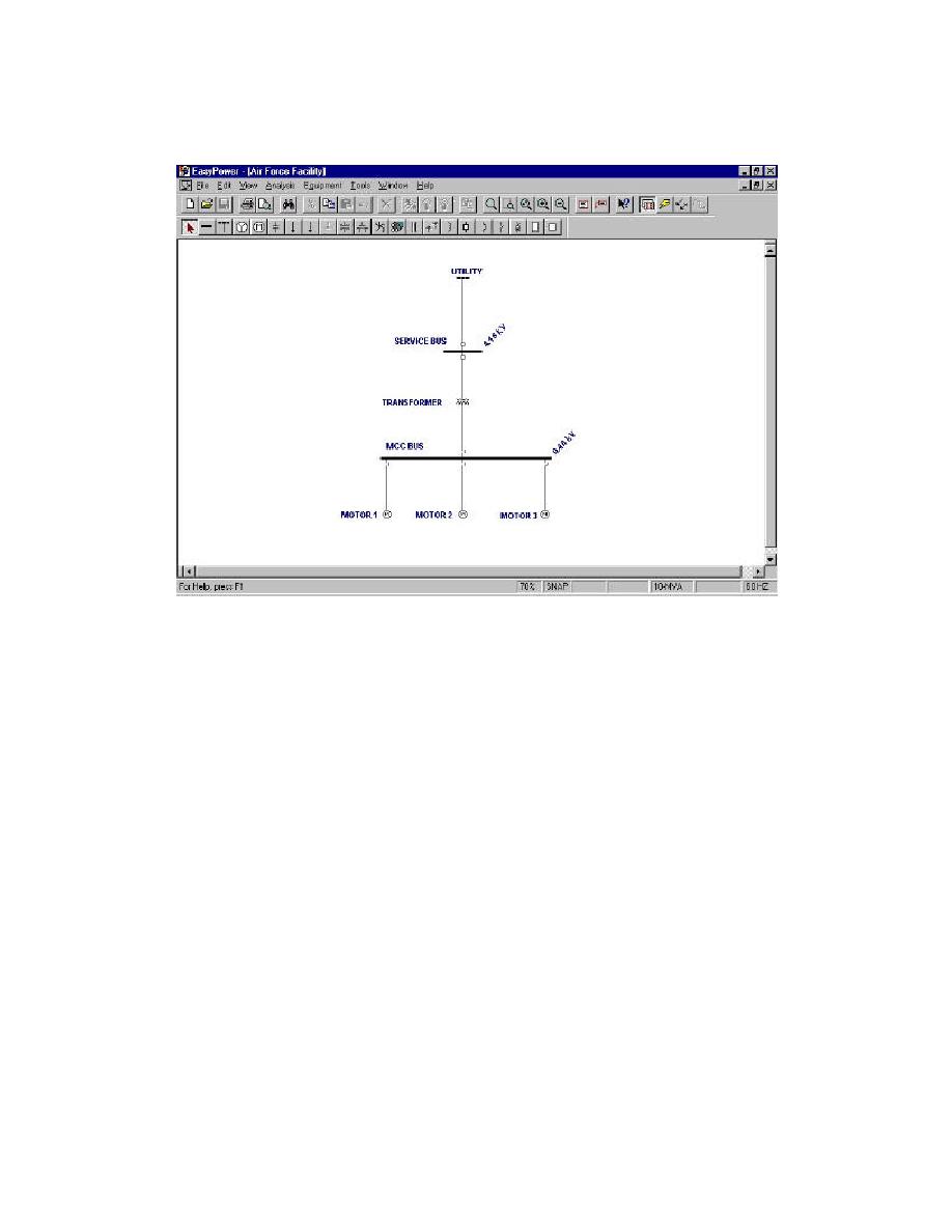
Figure 2-1. Computer Model of Electrical System
2-3.3
The computer program used for the analysis should have the following
minimum features:
2-3.3.1 A graphical user interface is recommended so that the electrical system is
shown on a one -line diagram representative of the ac tual facility electrical system.
Tabular presentations require too much effort to evaluate and users have difficulty
cross-referencing the results to the actual system one -line diagram.
2-3.3.2 The one-line diagram should include the flexibility to use the actual facility
equipment designations. The user should be able to readily find equipment on the
computer program one -line diagram without any need for cross-reference lists.
2-3.3.3 The program must perform power flow, short circuit, voltage drop, a nd motor
starting analyses as a minimum. Additional modules for electrical coordination and
harmonic analysis are desirable.
2-3.3.4 The program should readily identify overduty equipment in either power flow
or short circuit analysis modes. For example , in short circuit analysis mode, the
program should be capable of identifying breakers that are potentially exposed to short
circuit currents that exceed interrupting ratings. In power flow mode, overloaded
equipment or excessive voltage drop should be i dentified. Equipment sizing features
based on this information are desirable.
2-4


 Previous Page
