UFC 3 -520-01
June 10, 2002
6.0 kW
Corrected Battery Load (kW ) =
1.25 1.11 = 9.05 kW
0.92
Notice that the designer chose not to add design margin because the UPS is
already assumed to be fully loaded.
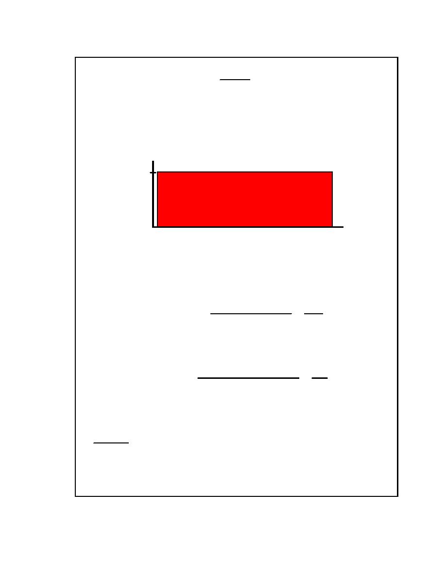
For this typical example, the duty cycle cons ists of the above constant load for 30
minutes.
9.05
Load
(kW)
0
30
Discharge Time (minutes)
The UPS maximum dc input voltage was specified as 140 volts. This voltage is
the maximum allowed voltage on the system. Also, assume that the
manufacturer recommends a maximum battery equalize voltage o f 2.33 volts per
cell. The maximum number of cells is given by:
Max System Voltage
140
Maximum Number of Cells =
=
= 60.09 cells
Equalize Voltage
2.33
In this case, choose 60 cells. Next, determine the minimum allowed voltage per
cell based on the system minimum voltage requirement of 105 volts:
Minimum System Voltage
105
Minimum Cell Voltage =
=
= 1.75 volts
Number of Cells
60
The designer needs 60 cells capable of providing 9.05 kW for 30 minutes without
allowing voltage to drop below 1.75 volts per cell. Each cell must deliver:
9.05 kW
= 0.151 kW per cell
60 cells
This is the information needed to select a cell from the manufacturer's d ata
sheets. Each cell must be capable of providing 0.151 kW for 30 minutes without
individual cell voltage falling below 1.75 volts.
E-2.3
Refer to IEEE 1184, IEEE Guide for the Selection and Sizing of Batteries for
Uninterruptible Power Supply Systems, for additional information regarding sizing of
UPS batteries.
E-6


 Previous Page
