UFC 3-535-01
17 November 2005
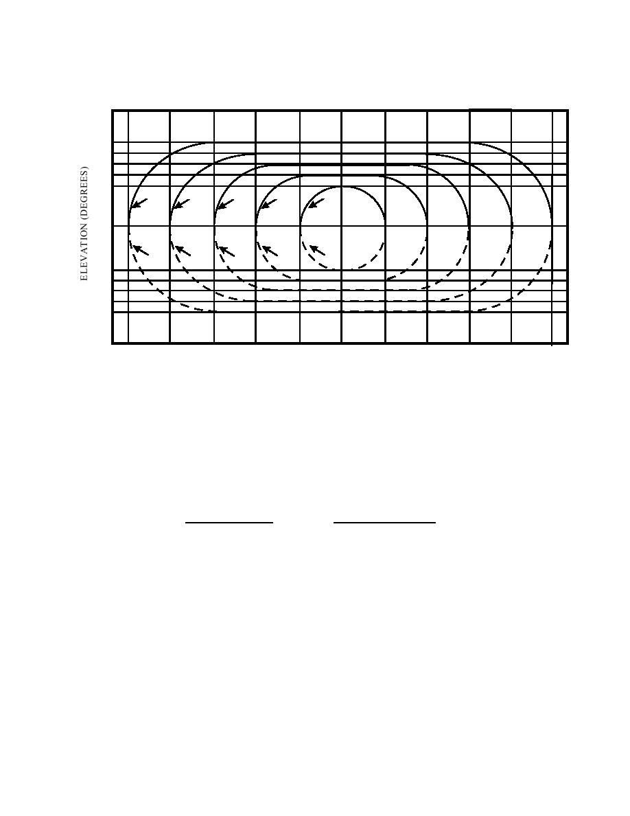
Figure 3-13. PAPI Photometric Requirements
+4
+3
+2
5,000 CD
30,000 CD
8,000 CD
14,000 CD
20,000 CD
WHITE
WHITE
WHITE
WHITE
WHITE
0
2,500 CD
4,000 CD
7,000 CD
10,000 CD
15,000 CD
RED
RED
RED
RED
RED
-2
-3
-4
10
8
6
4
2
0
2
4
6
8
10
AZIMUTH (DEGREES)
3-7.3.2
Aim PAPI units parallel with the approach within 0.5 degrees. Aim
successive light units in a light bar vertically, beginning with the out-board-most unit,
and incrementally at increasingly higher angles. The glide path angle is the mean of the
highest and lowest angle setting. (See Figure 3-14.) Set the angular difference between
successive light units as follows:
Approach Angle
Angular Difference
2 to 4 degrees
20 minutes
over 4 to 7 degrees
30 minutes
over 7 degrees
l degree
3-7.3.3
The location and alignment of the PAPI may be varied to meet local
conditions if the effective glide path is not less than 2.5 degrees or more than 4.0
degrees above the horizontal. Unless otherwise directed or where conditions dictate
otherwise, use 3.0 degrees for the design glide path angle. For design purposes, the
visual glide path begins at the PAPI Runway Reference Point (RRP), which is a point on
the runway centerline at the PAPI light bar (through lens center of light units) coinciding
with the elevation of the lens center of the light units, and projects into the approach at
the glide path angle. (See Figure 3-14.) On a precision instrument runway, aim the PAPI
at the same angle as the electronic glide path. For the Army only, this procedure must
be modified for runways that serve aircraft in height group 4 (Table
3-3); for these runways the distance of the PAPI from the threshold must equal the
distance to the electronic glide slope source plus an additional 300 feet. For the Air
42


 Previous Page
