UFC 3-535-01
17 November 2005
Force only, PAPI locating procedures will ensure a minimum safe wheel height above
the threshold for all height groups using the runway.
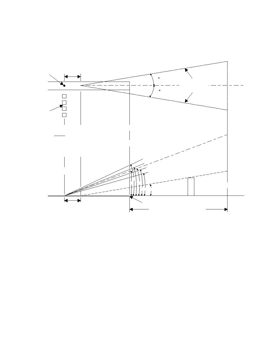
Figure 3-14. PAPI Aiming Criteria
90M
(300FT)
RRP
10
PAPI
CLEARANCE
PLANE
10
D
C
B
PAPI
A
WING BAR
A, B, C, D, = ELEVATION ANGLES FOR LIGHT UNITS
G = B + C = GLIDE PATH ANGLE
2
H
PAT
E = G - 1.2 = PAPI CLEARANCE PLANE ANGLE
CH
ROA
RRP = RUNWAY REFERENCE POINT
PP
PI A
T = THRESHOLD CLEARANCE HEIGHT
PA
ANE
RRP
NCE PL
EARA
PAPI CL
D
C
G
T
OBSTRUCTION
BA E
THRESHOLD
90M
(300FT)
6.4KM (4 STATUTE MILES)
PAPI
WING BAR
3-7.4
Considerations
Siting a PAPI must consider, as a minimum, the following: existing or planned ILS glide
slope; the established glide path (aiming angle, typically 3 degrees); the threshold
crossing height (TCH) for the selected aircraft height group; and the runway gradient
(longitudinal slope) from the threshold to the PAPI location.
3-7.4.1
With an ILS glide slope, the PAPI is located the same distance from the
runway threshold as the virtual source of the glide slope, within a tolerance of 10
meters (30 feet), and aimed at the same angle as the ILS glide slope. The virtual
source is the Runway Point of Intercept (RPI), where the glide path intercepts the
ground elevation along the runway centerline. For Army airfield only, this is modified for
aircraft in the height group #4 (Table 3-3), in which case the PAPI is sited at the RPI
plus an additional 90 meters (300 feet), +15 meters 0 meters (+50 feet, -0 feet) from
threshold. [See paragraph 12-3 for siting PAPI.]
43


 Previous Page
