UFC 3-535-01
17 November 2005
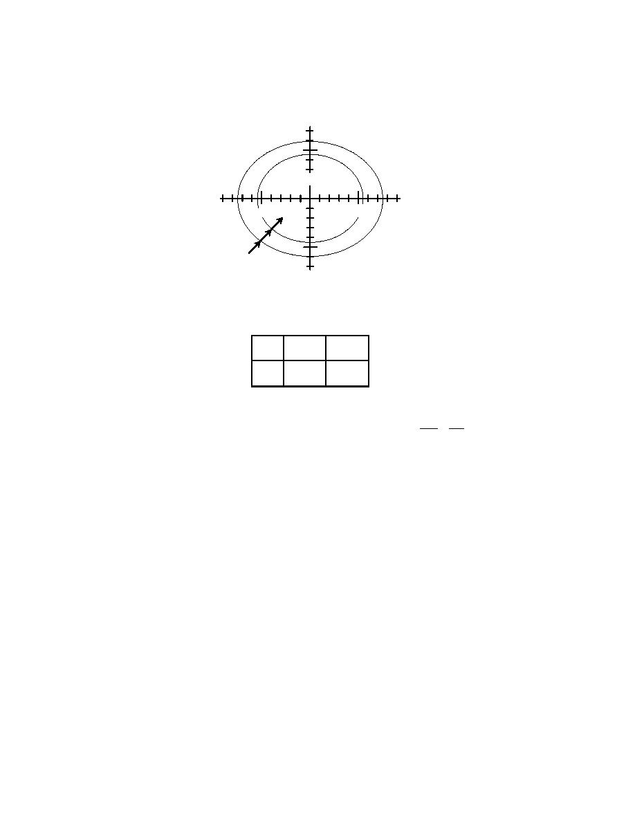
Figure 4-5. Threshold Light Photometric Requirements
DEGREES
VERTICAL
5
II
I SEE NOTE 2
DEGREES
HORIZONTAL
5
5
SEE NOTES
5
1, 3 & 4
THRESHOLD LIGHTS, GREEN
I=50% II=10%
5.5
7.5
a
4.5
6.0
b
NOTES:
X2 Y2
1. ALL CONTOURS ARE ELLIPSES CALCULATED BY EQUATION 2 + 2 = 1
a
b
2.
THE MINIMUM AVERAGE CANDELA IN GREEN LIGHT OF THE MAIN BEAM IS 10,000 CD
FOR HIGH INTENSITY SYSTEMS AND 100 CD FOR MEDIUM INTENSITY SYSTEMS.
3.
MAXIMUM INTENSITY MUST NOT EXCEED 3 TIMES AVERAGE CANDELA SPECIFIED
AND THE AVERAGE INTENSITY MUST NOT EXCEED 1.5 TIMES THE MINIMUM
AVERAGE INTENSITY SPECIFIED.
4.
PORTIONS OF THE LIGHT BEAM CUT OFF BY THE MOUNTING SURFACE MAY BE
DISREGARDED.
4-5
LIGHTING WITH DISPLACED THRESHOLDS
4.5.1
General
The threshold, which is the beginning of the landing area, may not be located at the
beginning of the full strength runway pavement. It may be displaced because of
obstructions or other operational problems. The area of full strength pavement in front of
the threshold may be required for takeoff or for rollout on landings from the opposite
direction. Where this occurs, changes to the standards for runway lighting are required.
4-5.2
Configuration for Permanent Displacement
See Figures 4-6 and 4-7 for typical layouts of displaced thresholds.
57


 Previous Page
