UFC 3-535-01
17 November 2005
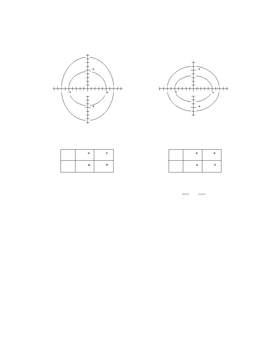
Figure 4-12. Runway Centerline Light Photometric Configuration
DEGREES
VERTICAL
DEGREES
VERTICAL
5
5
II
I
DEGREES
HORIZONTAL
5
5
SEE NOTE 2
5
SEE NOTE 2
5
5
5
A. CENTERLINE LIGHTS, HOOK-RESISTANT,
B. CENTERLINE LIGHTS, HIGH-INTENSITY,
7.5M (25FT) SPACING
15M (50FT) SPACING
I=50% II=10%
I=50% II=10%
a
5.0
7.0
a
5.0
7.0
b
4.5
8.5
b
3.5
6.0
NOTES:
2
2
1. ALL CONTOURS ARE ELLIPSES CALCULATED BY EQUATION X
Y
=1
+
2
a
2
b
2. THE MINIMUM AVERAGE INTENSITY OF THE MAIN BEAM (INSIDE CONTOUR I ) IS FOR
7.5M (25FT) SPACING, 250 CD (WHITE) AND 250 CD (RED); AND FOR 15M (50FT) SPACING
5000 CD AND 750 CD (RED). MAXIMUM INTENSITY SHOULD NOT EXCEED 1.5 TIMES
ACTUAL AVERAGE INTENSITY.
3. MINIMUM INTENSITY OF I=50% AND II=10% OF REQUIRED MAIN BEAM INTENSITY.
4-8
TOUCHDOWN ZONE LIGHTS (TDZL)
4-8.1
Purpose
Touchdown zone lights provide continuity when crossing the threshold into the
touchdown area and provide visual cues during the flare out and touchdown phases of
the landing. They are required for Category II or III operations.
4-8.2
Configuration
The touchdown zone lighting system presents, in plain view, two rows of high intensity
light bars arranged symmetrically about the centerline of the runway. The two rows of
light bars are located within the paved area of the runway in order to define that portion
of the landing area used for flare and touchdown. The system extends from the
threshold of the usable landing area toward the upwind end of the runway, a distance of
900 meters (3,000 feet). The light bars are in rows at 30 meter (100 foot) intervals. Each
70


 Previous Page
