UFC 3-535-01
17 November 2005
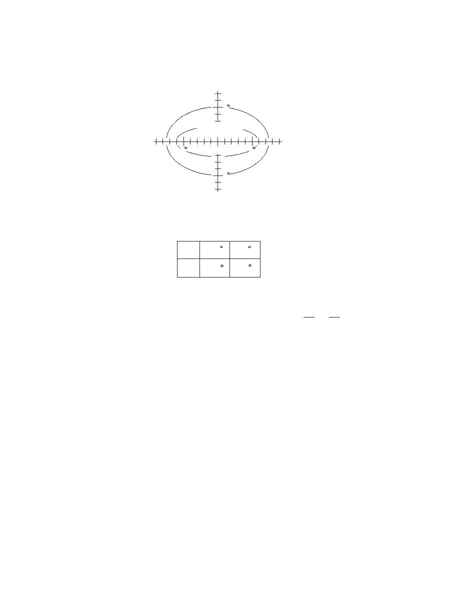
Figure 4-10. Runway End Light Photometrics
DEGREES
VERTICAL
5
II
MIN. AVERAGE
I
2500 CD
DEGREES
HORIZONTAL
5
5
SEE NOTE 2
5
RUNWAY END LIGHT, RED
I=50% II=10%
a
6.0
7.5
b
2.25
5.0
NOTES:
2
2
X
+ Y2 =1
1. ALL CONTOURS ARE ELLIPSES CALCULATED BY EQUATION
a2
b
2. THE MINIMUM AVERAGE INTENSITY OF THE MAIN BEAM (INSIDE CONTOUR I ) IS
2,500 CD, AVIATION RED. MAXIMUM INTENSITY SHOULD NOT EXCEED 1.5 TIMES
ACTUAL AVERAGE INTENSITY.
3. MINIMUM INTENSITY OF I=50% AND II=10% OF REQUIRED MAIN BEAM INTENSITY.
4-6.4
Equipment
Unless the lights are to be located in an area not paved, use in-pavement fixtures with
no part protruding more than 0.025 meters (1 inch) above the surrounding surface.
Where the runway end is co-located with the opposite direction threshold, the threshold
and runway end lights may not be incorporated into the same fixture unless the
photometrics meet the requirements for both the red and green colors. (See paragraph
13-10.4.)
4-6.5
Compliance with International Military Standards
4-6.5.1
NATO
These standards meet NATO STANAG 3316.
66


 Previous Page
