UFC 3-535-01
17 November 2005
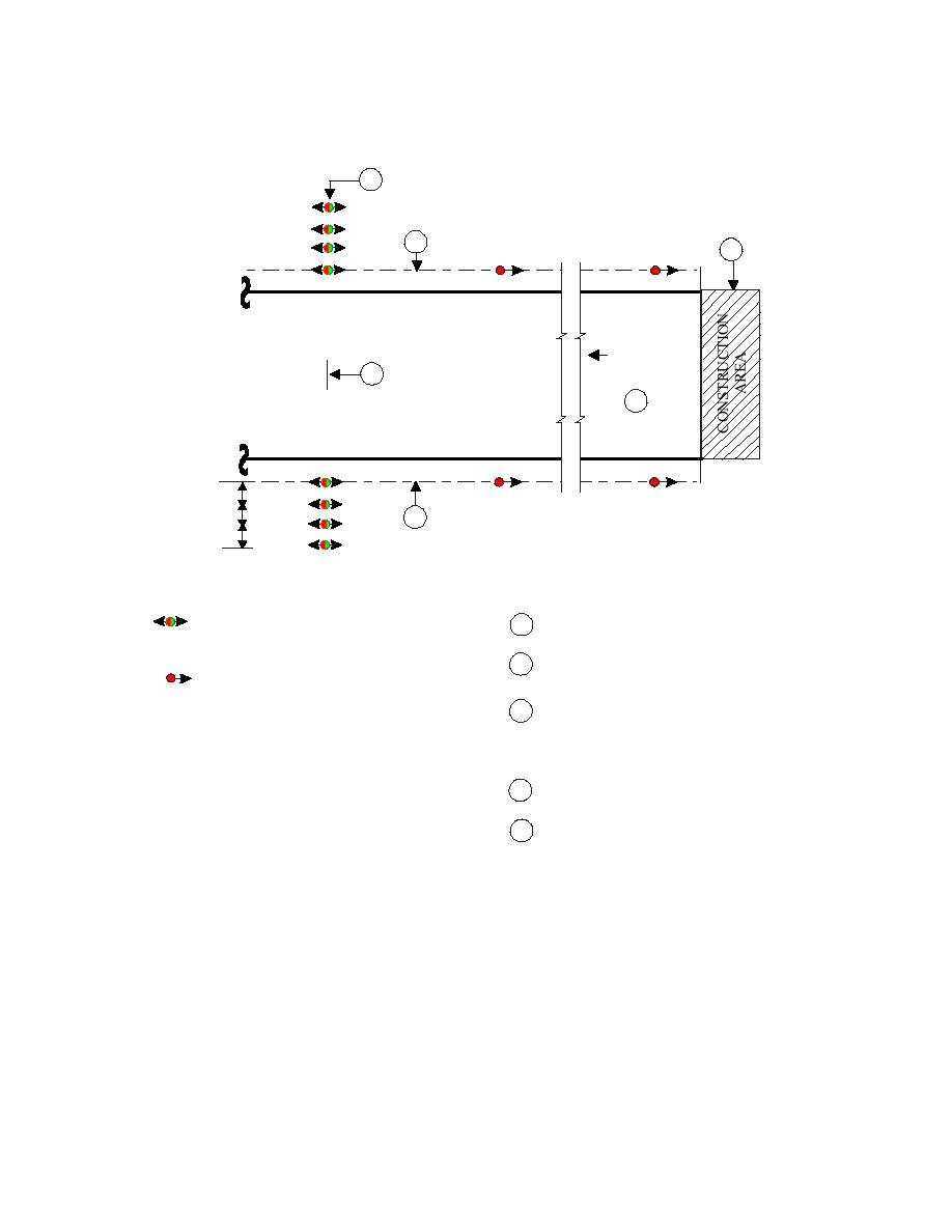
Figure 4-9. Displaced Threshold Lighting with Co-located
Threshold/End of Runway Lights (Temporary)
3
TEMPORARY END OF RUNWAY
R
G
1
R
G
5
R
G
R
R
R
G
DIRECTION
OF
2
APPROACH
4
RUNWAY
MINIMUM 300 M (1000 FT) OVERRUN
R
G
R
3 SPACES
R
@ 3M (10FT)
1
R
G
EACH
R
G
R
G
LEGEND:
NOTES:
THRESHOLD LIGHT, PLANK MOUNTED.
1
RUNWAY EDGE LIGHT LINE.
G
R
BI-DIRECTIONAL RED/GREEN.
INDICATES LOCATION OF THRESHOLD
2
RED TOWARD APPROACH
R
OF USABLE LANDING AREA.
(WHITE TOWARD RUNWAY IF
USEABLE FOR ROLL-OUT,
LINE OF THRESHOLD LIGHTS MARKING
3
STOP-WAY OR TAXIWAY)
LOCATION OF THRESHOLD OF USABLE
LANDING AREA. TEMPORARY END OF
RUNWAY.
EXISTING APPROACH/THRESHOLD
4
LIGHTS DISCONNECTED.
CONSTRUCTION AREA.
5
4-5.3.4
Install temporary runway end lights, as specified in paragraph 4-6, with
dimensions referenced from the end of the usable takeoff and rollout area.
NOTE: When temporary displacement is due to construction work, place the runway
end lights to allow an additional 1,000 feet for emergency roll-out or to protect the
Approach-Departure Clearance Surface from the tallest equipment that will be erected
in the approach-departure zone. See UFC 3-260-01 for geometric requirements of the
Approach-Departure Clearance Surface.
4-5.3.5
All fixtures are elevated and may be stake mounted or mounted on planks
fastened to the runway surface.
63


 Previous Page
