MIL-HDBK-1025/10
Relation of Ship's Electrical Service Components. An understanding of the
9.3
physical and electrical arrangements of these components is necessary in understanding the safety
problems involved in the basics of utilizing portable power cables to feed shore electrical power to
a ship's electrical bus.
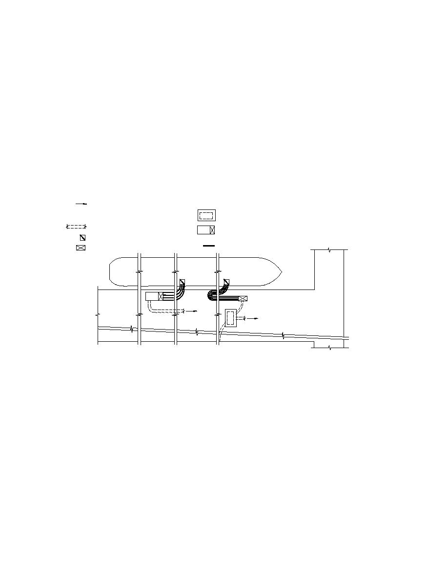
9.3.1 Equipment Physical Relationships. Figure 13 indicates diagrammatically the
physical relation of the ship and its power cable connections to the pier electrical power service.
Ships may have one, two, or three service ports requiring connections to pier electrical outlets.
Power cables need to be positioned to be of equal length and without sharp bends. Power cables
may need protection as covered later.
SYMBOLS
To shore medium-voltage distribution system or to 15-kv disconnect
assembly
Skid-mounted substation with pier electrical outlets
Duct line under pier
Substation in below pier vault
Ship's bus service port
Pier electrical outlet assembly
Shore-to-ship cables
SHIP
SHORE
PIER
Figure 13
Shore-to-Ship Portable Power Cable Location Diagram
9.3.2 Electrical Circuit Arrangement. Figure 14 shows a simplified one-line diagram
covering the ship's main electrical service components. Service components consist of those
whose safety aspects are generally covered by Sections 6 and 8 and those that are covered
specifically in this section. A vault substation is shown. Circuit is similar for skid-mounted
substations except without vault requirements. Pier outlet assembly may be part of a skid-
mounted substation. Primary selective system shown is preferred system but is not always
provided.
9.3.2.1 General Electrical System Safety. The maintenance and operation safety
aspects of the medium-voltage distribution system, substations, vaults, and low-voltage cables in
duct lines is covered in previous sections.
134


 Previous Page
