TM 5-810-15
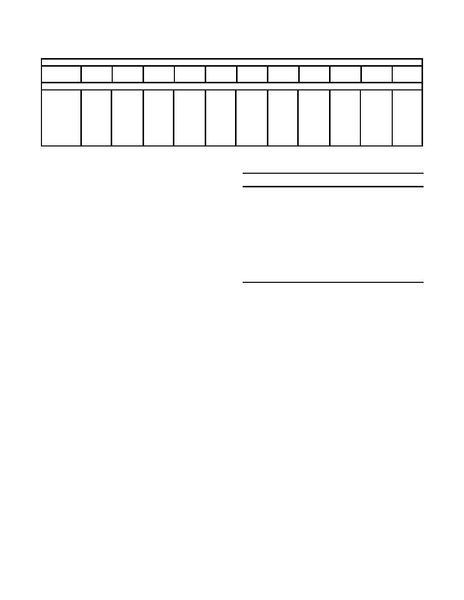
Table 8-5. Recommended Economic Thickness for Pipe Insulation. (Continued)
Temperature of pipe F
Nominal Pipe
size, in.
100-199
200-299
300-399
400-499 500-599 600-699 700-799
800-899
900-999 1000-1099 1100-1200
UTILITY--STEAM GENERATION
7
1
1
2
2
2
2
3
3
3
4
4
8
1
1
2
2
2
2
3
3
4
4
4
9
1
1
2
2
2
3
3
3
4
4
5
10
1
1
2
2
3
3
3
4
4
4
5
11
1
1
2
2
3
3
3
4
4
4
5
12
1
1
2
2
3
3
3
4
4
4
5
l4 and up
1
1
2
2
3
3
4
4
4
4
5
8-5. Pipe hangers, anchors and supports.
Table 8-6. Piping Velocity Guidelines.
will be designed to meet ASME B31.1 require-
Fluid
Application
Velocity
ments where applicable. Pipe hangers will be in
Steam
Superheated steam, boiler leads
150-333 fps
accordance with MSS SP-69.
Auxiliary steam, exhaust lines
100-250 fps
b. Spacing. Guidelines for pipe support spacing
and carrying capacities are provided in ASME
Saturated and low pressure steam
100-167 fps
B31.1
Water
Centrifugal pump suction lines
3-5 fps
8-6. Pipe expansion compensation.
Feedwater
8-15 fps
a. Design. The thermally induced expansion of
General service
4-10 fps
piping materials can be compensated for with
Potable water
Up to 7 fps
normal pipe bends and the proper placement of
anchors. The thermal expansion of common piping
without exceeding maximum allowable velocities or
materials is shown in Appendix B of the ASME
causing excessive pressure drops.
B31.1.
e. Sizing calculations. Empirical equations and
b. Expansion devices. When piping system de-
charts have been devised to calculate pressure
sign is unable to compensate for pipe expansion,
drops with reasonable accuracy. The Darcy Equa-
expansion bends or expansion joints will be used.
tion has been shown to produce accurate results.
Expansion joints and bends will conform to ASME
standards.
8-8. Steam traps.
a. Application. Steam traps are devices that are
8-7. Pipe sizing.
used to accomplish the following functions:
a. General. Selection of the proper pipe size for
(1) Allow condensate resulting from loss of
any particular application is dependent upon nu-
latent heat in steam to flow from the steam system
merous variables. Pipe sizing is based on velocity,
to a lower pressure system or to atmosphere.
pressure loss, and friction loss calculations.
(2) Vent air and other gases from the steam
b. Data requirements. In order to properly size
system to maintain steam temperature and reduce
piping, pertinent data must be organized for use in
corrosion.
the required calculations. This data includes pipe
(3) Prevent escape of steam from the steam
material (friction factor), process fluid, flow re-
system.
quirements, design pressures and temperatures,
b. Selection. The factors to be considered when
allowable pressure drop, velocity requirements, and
selecting the proper steam trap include condensate
preliminary piping layout.
load, continuous or intermittent operation, system
c. Velocity guidelines. General guidelines for
pressure, constant or variable pressure and load,
indoor or outdoor installation, failure mode (open
allowable velocities in piping systems are shown in
or closed), air and noncondensible gas venting, and
table 8-6.
resistance to water hammer.
d. Pipe sizing philosophy. Piping will be sized to
c. Design. Trap selection and sizing depends on
obtain a maximum velocity that corresponds to the
many factors. The condensate load on a trap
allowable pressure drop for the system. It is
involves range of load as well as rate of change.
desirable to keep velocities as high as possible
Nearly all traps service a long range. A trap will be
8-11


 Previous Page
