TM 5-810-15
substituted for faulty units which are encountered
writing specifications. Data rates of approximately
during start-up and operation of the plant. For
1 mega baud are available.
critical subsystems consideration should be given to
redundant microprocessors with automatic
9-2. Combustion controls.
switching of inputs and outputs from one
a. General. The purpose of combustion control
microprocessor to another. The data highway
systems is to modulate the quantity of fuel and
should be looped or redundant so that failure of a
combustion air inputs to the boiler in response to a
segment of the data highway will not result in the
load index or demand (steam pressure or steam
loss of communications. Control elements should
flow) and to maintain the proper fuel/air ratio for
be designed to fail in a safe condition upon loss of
safe and efficient combustion for the boiler*s entire
the electric or pneumatic power to the actuators or
load range.
input signal. The loss of power at the component or
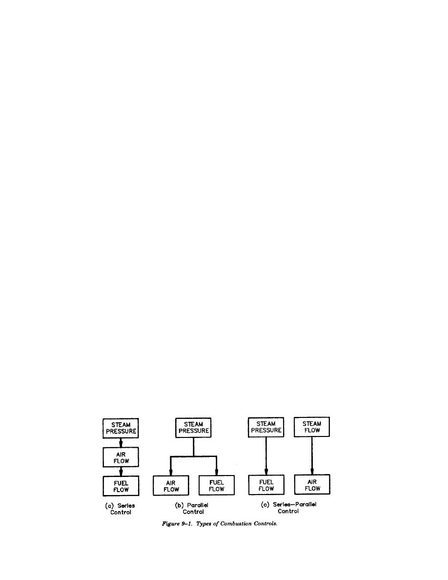
b. System types. Three types of combustion con-
subsystem levels must cause the associated
trol systems are available: series, parallel, and
auto/manual stations to switch to the manual mode
series-parallel. Each of these types are schemati-
of operation. The control logic should have
cally represented in figure 9-1.
continuous self diagnostic capability and, upon
(1) Series control. A series control system as
detection of component failure, transfer to manual
shown in figure 9-1(a) uses variation in the steam
and indicate the cause of the failure.
header pressure (or any other master demand
Microprocessors are to contain nonvolatile memory
signal) from the setpoint to cause a change in the
which will not be erased on power failure.
combustion air flow which, in turn, results in a
e. Control system expansion. The control system
sequential change in fuel flow. The use of series
architecture should allow expansion at all levels of
control is limited to boilers of less than 100,000
the system. The 110 can be expanded by installing
pph that have a relatively constant steam load and
additional cards or racks with signal conditioning
a fuel with a constant Btu value.
for communication to the control system process-
(2) Parallel control. A parallel control system
ing units. Additional nodes can be added to the
as shown in figure 9-1(b) uses a variation from
data highway to allow additional processing units,
setpoint of the master demand signal (normally
engineering work stations, and operator interface
steam pressure) to simultaneously adjust both the
CRT*s to be added to the control system.
fuel and combustion air flows in parallel. This type
f. Data link. The process 110 signals are con-
of system is applicable to stoker-fired boilers,
nected to the termination units and through signal
pulverized coal fired boilers, gas/oil fired boilers
conditioners to the microprocessor controllers. The
and atmospheric circulating fluidized bed (ACFB)
control system data highway for exchange of data
boilers.
between microprocessor based controllers and be-
(3) Series-parallel control. A series-parallel
tween microprocessor based controllers, data
control system as shown in figure 9-1(c) should be
acquisition systems, operator interface and
used to maintain the proper fuel/air ratio if the Btu
engineering work stations will be redundant. The
value of the fuel varies by 20 percent or more, if
data highways will utilize coax, twines of fiber
the Btu input rate of the fuel is not easily
optic cabling. The speed of data transmission is
monitored, or if both of these conditions are
increasing and should be investigated prior to
present. These conditions normally exist on pulver-
9-2


 Previous Page
