TM 5-810-15
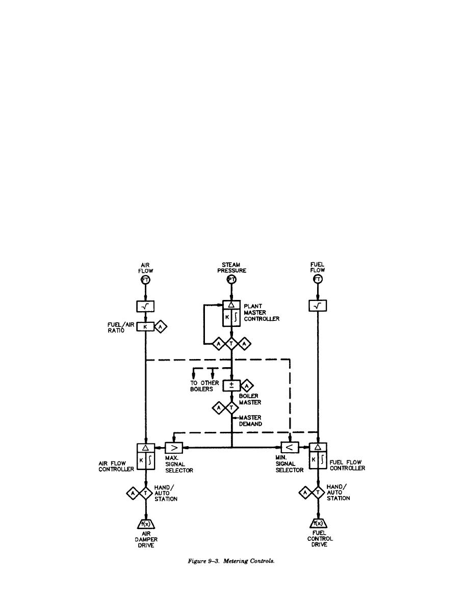
(2) Metering control. Metering control
e. Stoker system controls.
(1) Fuel flow control. The components of a
systems regulate combustion based on metered fuel
and air flows as shown in figure 9-3. The master
stoker system must respond to the fuel flow de-
demand developed from steam pressure error
mand signals generated by the combustion control
establishes the setpoints for fuel and combustion air
system. For spreader stokers the coal feed to the
flows at the controllers. The controllers drive the
overthrow rotor will vary with the demand signal.
final control elements to establish proper fuel and
Grate speed on traveling grate and traveling chain
flows which are fed back to the controllers.
grate stokers will respond to the demand signal.
Maximum and minimum signal selectors are used to
The frequency and duration of vibration cycles on
prevent the fuel input from exceeding available
vibrating grate stokers will vary with the demand
combustion air on a boiler load increase and to
signal. In all cases the relationship between fuel
prevent combustion air from decreasing below fuel
flow and unit load will be determined for use in the
flow requirements on load reduction. This system
combustion control system to properly control fuel
is a cross-limiting flow tie back system with air
flow in response to the demand signal.
(2) Combustion air control. The combustion
leading fuel on load increase and fuel leading air on
load reduction. This system is applicable to gas and
air flow is normally controlled at the FD fan. Two
oil, pulverized coal, and ACFB fired units.
methods that are commonly used are control of
d. System selection. Table 9-1 summarizes the
inlet vanes on the FD fan or control of the FD fan
combustion control systems discussed and their
inlet damper. If a metering control system is used
application to the various types of boilers.
the combustion air flow should be measured down
9-4


 Previous Page
