TM 5-810-15
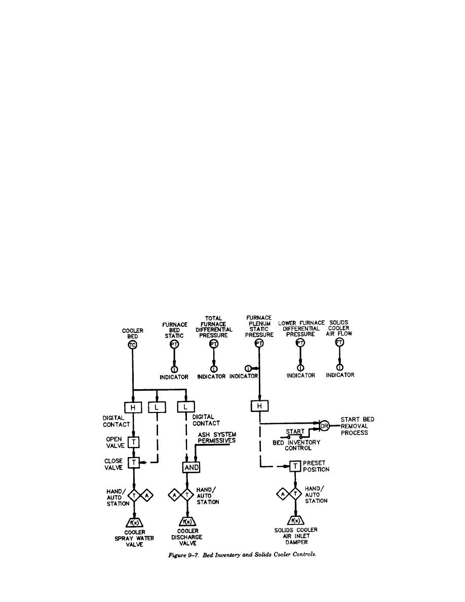
furnace plenum static pressure and lower furnace
control valve and downleg aeration and plenum
differential are all monitored to give the operator
control valves.
(a) J-valve pressure control. The J-valve
an indication that the furnace bed inventory should
be reduced. When a sequence for removal of
blower pressure is maintained by sensing pressure
materials is initiated the solids cooler air flow
downstream of the J-valve blower discharge
control dampers are opened to a preset position.
damper. The discharge damper is modulated to
The air flow dampers position will start a cycle
maintain a constant pressure of approximately
timer and open the bed material transfer line. At the
170". The upleg and downleg plenum air is main-
end of the timed period the transfer line is closed.
tained at a constant value of approximately 400
The material is cooled by spray water and air flow
lb/hr. The setpoint is constant throughout the load
to a temperature suitable for the ash system. The
range. Upleg and downleg plenum air flow will be
spray water valve opens and closes automatically
measured with a Venturi section or air foil flow
based on cooler bed temperature. After the bed
element in the ductwork to the plenums. The flow
material is cooled it is placed in a hopper for
element will be designed to provide a design
removal by the ash system. The air flow dampers
differential pressure across the flow element of not
and solid spray water valve can be opened and
less than 2 inches wg.
(b) J-valve aeration valve control. The
closed manually by a hand auto station. Figure 9-7
shows the solids cooler temperature and flow
measured air flow is compared to the constant
control.
setpoint and the control dampers modulated to
(6) J-valve blower control. The J-valve blower
maintain the air flow at setpoint. The downleg
control maintains air flow for fluidization and
static pressure, inlet static pressure, and upleg
transport of material from the hot cyclone to the
static pressure outlet as well as differential pressure
furnace. The J-valve control is shown on figure 9-
across portions of the J-valve indicate solids flow,
8. The system includes J-valve blower discharge-
density and dipleg differential are measured and are
pressure control valve, upleg aeration and plenum
utilized to allow the operator to manually control
9-9


 Previous Page
