UFC 3-440-01
14 June 2002
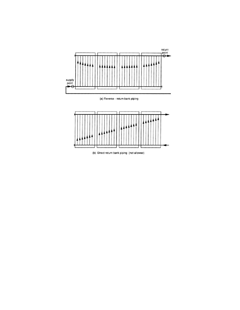
Figure 4-3. Reverse-Return Versus Direct-
Return Piping Strategies
4.2.2.3.2
Stepped Collector Rows. Note that true reverse-return is not possible for
stepped collector rows. The reason is that extra pipe length is required to reach the
roof level supply and return manifolds up to and back from the elevated bank inlets and
outlets. However, the same diagonal attachment strategy should be used and the extra
pipe length for each elevation should be accounted for in the pressure drop/pump sizing
calculation.
4-2.2.4
Array Layout and Piping Schematic. The final array layout should be
determined using the methodology discussed under paragraph 3-4. If the dimensions
of the collector to be specified differ from those used to perform the estimated roof area
calculations, the array layout will need to be performed based on the collector
specification and the unshaded roof area available. The designer has the option to
decide which collector grouping is best within the guidelines requiring that the actual
collector area be plus or minus 10 percent of the calculated area from the thermal
analysis. For the example given under paragraph 3-4, the deviation is a 6 percent area
increase from the 26 to 28-collector case. The next smallest collector areas would have
required 25 or 24 collectors, representing 5 and 9 percent decreases, respectively. The
24-collector case may be preferred over the 25-collector option since more variations
are possible for the array layout. With this array layout and using the reverse-return
piping strategy discussed earlier, piping schematics similar to those shown in Figure 4-4
and Figure 4-5 can be determined. The array layout and piping schematic should be
noted in the construction drawings to alert the contractor to pipe the array exactly as
4-6


 Previous Page
