TM 5-805-4/AFJMAN 32-1090
they are not inadvertently short-circuiting the
integral concrete inertia block. (Unless specified
spring mounts.
otherwise, all concrete referred to in this manual
should have a density of at least 140 to 150 lb/ft.3.)
(b) All building trash should be removed
from under the isolated base of the equipment.
(1) The length and the width of the inertia
Loose pieces of grout, 2x4s, nuts, bolts, soft drink
block should be at least 30 percent greater than
bottles, beer cans, welding rods, pipes, and pipe
the length and width of the supported equipment.
couplings left under an equipment base can short-
(2) Mounting brackets for stable steel springs
circuit the isolation mounts. It is recommended
should be located off the sides of the inertia block
that a 2 inch to 4 inch clearances be provided
at or near the height of the vertical center-of-
under all isolated equipment in order to facilitate
gravity of the combined completely assembled
inspection and removal of trash from under the
equipment and concrete block. If necessary, curbs
base.
or pedestals should be used under the base of the
(c) For many equipment installations, there
steel springs in order to bring the top of the loaded
is no need to bolt down the isolation mounts to the
springs up to the center-of-gravity position. As an
floor because the smooth operation of the machine
alternative, the lower portion of the concrete iner-
and the weight of the complete assembly keep the
tia block can be lowered into a pit or cavity in the
system from moving. For some systems, however,
floor so that the steel springs will not have to be
it may be necessary to restrain the equipment
mounted on curbs or pedestals. In any event, the
from "creeping" across the floor. In these situa-
clearance between the floor (or all the surfaces of
tions, it is imperative that the hold-down bolts not
the pit) and the concrete inertia block shall be at
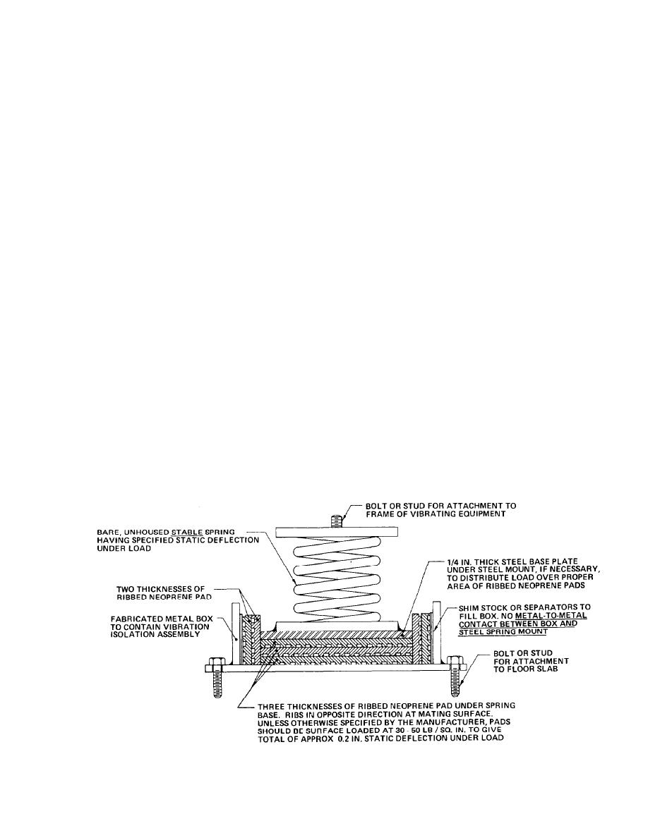
short circuit the pads. A suggested restraining
least 4 inches, and provision should be allowed to
arrangement is illustrated in figure 8-1. Simpler
check this clearance at all points under the block.
versions can be devised.
(3) Floor slab thickness. It is assumed that
(d) For buildings located in earthquake-
MER upper floor slabs will be constructed of dense
concrete of 140-150 lb/ft.3 density, or, if lighter
prone areas, the isolation mounts should contain
snubbers or motion-limiting devices that restrain
concrete is used, the thickness will be increased to
the equipment against unusual amounts of move-
provide the equivalent total mass of the specified
ment. These snubbers should be set to provide
floor. For large MERs containing arrays of large
adequate free movement for normal equipment
and heavy equipment, it is assumed that the floor
operation. These devices are available from most
slab thickness will be in the range of 8 to 12
suppliers of isolator equipment.
inches, with the greater thicknesses required by
b. Type I mounting assembly. The specified
the greater floor loads. For smaller MERs contain-
equipment should be mounted rigidly on a large
ing smaller collections of lighter weight but typi-
Figure 8-1. Suggested Arrangement of Ribbed Neoprene Pads for Providing Resilient Lateral Restraint to a Spring Mount.
8-4


 Previous Page
