TM 5-805-4/AFJMAN 32-1090
manufacturer for the particular densities or duro-
there is an acoustically critical area immediately
meters involved. In general, most of these pads are
below the cooling tower (or within about 25 feet
horizontally on the floor immediately under the
intended for load rates of 30 to 60 psi, and if they
are underloaded (for example, at less than about
tower). It is necessary to provide limit stops on
10 psi), they will not. be performing at their
these springs to limit movement of the tower when
maximum effectiveness.
it is emptied and to provide limited movement
f. Type V mounting assembly (for propeller-type
under wind load.
(4) Pad materials, when used, should not be
cooling towers located on roof decks of large
short-circuited by bolts or rigid connections. A
buildings may produce serious vibration in their
schematic of an acceptable clamping arrangement
buildings if adequate vibration isolation is not
for pad mounts is shown in figure 8-3. Cooling
provided. In extreme cases, the vibration may be
tower piping should be vibration-isolated in accord-
evident two or three floors below the cooling
ance with suggestions given for piping.
towers.
8-4. Tables Of Recommended Vibration Isola-
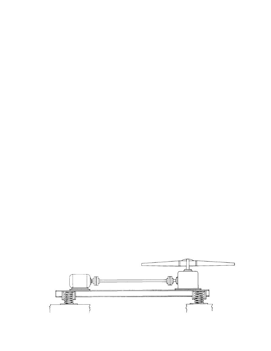
(1) It is recommended that the motor, drive
tion Details.
shaft, gear reducer, and propeller be mounted as
a. Table format. A common format is used for
rigidly as possible on a "unitized" structural sup-
port and that this entire assembly be isolated from
all the tables that summarize the recommended
the remainder of the tower with stable steel
vibration isolation details for the various types of
springs in accordance with table 8-8. Adequate
equipment. A brief description of the format is
clearance between the propeller tips and the cool-
given here.
(1) Equipment conditions. The three columns
ing tower shroud should be provided to allow for
starting and stopping vibrations of the propeller
on the left of the table define the equipment
assembly. Several of the cooling tower manufactur-
conditions covered by the recommendations: loca-
ers provide isolated assemblies as described here.
tion, rating, and speed of the equipment. The
This type of mounting arrangement is shown
rating is given by a power range for some equip-
schematically in figure 8-2.
ment, cooling capacity for some, and heating ca-
(2) In addition, where the cooling tower is
pacity for some. The rating and speed ranges
located on a roof deck directly over an acoustically
generally cover the range of equipment that might
be encountered in a typical building. Subdivisions
critical area, the structureborne waterfall noise
in rating and speed are made to accommodate
may be objectionable; it can be reduced by locating
variations in the isolation. If vibrating equipment
three layers of ribbed or waffle-pattern neoprene
between the base of the cooling tower and the
is supported or hung from an overhead floor slab,
supporting structure of the building. This treat-
immediately beneath an acoustically critical area,
ment is usually not necessary if there is a noncri-
the same degree of vibration isolation should be
tical area immediately under the cooling tower.
provided as is recommended for the location desig-
(3) A single-treatment alternate to the com-
nated as "on upper floor above critical area".
bined two treatments of (1) and (2) above is the
Similarly, if the vibrating equipment is hung from
an overhead floor slab beneath a noncritical area,
isolation of the entire cooling tower assembly on
stable steel springs, also in accordance with table
the same vibration isolation should be provided as
is recommended for the location designated as "on
8-8. The springs should be in series with at least
two layers of ribbed or waffle-pattern neoprene if
upper floor above noncritical area".
Figure 8-2. Schematic of Vibration Isolation Mounting for Fan and Drive-Assembly of Propeller-Type Cooling Tower.
8-6


 Previous Page
