TM 5-805-4/AFJMAN 32-1090
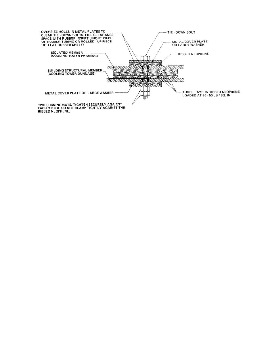
Figure 8-3. Schematic of a Resilient Clamping Arrangement With Ribbed Neoprene Pads.
(2) Mounting recommendations. The three col-
piece of equipment remote from other equipment,
umns on the right of the table summarize three
the recommendations can be relaxed, either by
basic groups of recommendations: Column 1, the
decreasing the static deflection of the mount or by
type of mounting; Column 2, the suggested mini-
decreasing the weight of the inertia block or even
mum ratio of the weight of the inertia block (when
by eliminating the inertia block where a critical
required) to the total weight of all the equipment
area is not involved.
mounted on the inertia block; and Column 3, the
(d) Resilient support of all piping connected
suggested minimum static deflection of the isolator
to vibrating equipment should be in accordance
to be used.
with paragraph 8-5a. This recommendation ap-
(a) When the weight of the inertia block is
plies to the mounting of each piece of vibrating
being considered, the larger weight of the range
equipment, even though it is not repeated below
given should be applied where the nearby critical
for each piece of equipment.
area is very critical, or where the speed of the
b. Centrifugal and axial-flow fans. The recom-
equipment is near the lower limit of the speed
mended vibration isolation mounting for fans are
range given or the rating of the equipment is near
given in table 8-2. Ducts should contain flexible
the upper limit of the rating range. Conversely,
connections at both the inlet and discharge of the
the lower end of the weight range may be applied
fans, and all connections to the fan assembly
where the nearby critical area is less critical, or
should be clearly flexible. The entire assembly
where the speed is near the upper limit of the
should bounce with little restraint when one jumps
speed range or the rating is near the lower limit of
up and down on the unit. Where supply fan
the rating range.
assemblies are located over critical areas, it is
(b) When the static deflection of the isola-
desirable to install the entire inlet casing and all
tors is being considered, these minimum values
auxiliary equipment (coil decks and filter sections)
are keyed to the approximate span of the floor
on floated concrete slabs. The floated slab may
beams; that is, as the floor span increases, the
also serve to reduce airborne noise from the fan
floor deflection increases, and therefore the isola-
inlet area into the floor area below. Large ducts
tor deflection must increase. The specific minimum
(cross-section area over 15 sq feet) that are located
deflection in effect specifies the type of isolator
within about 30 feet of the inlet or discharge of a
that can be used; refer to table 8-1 for the normal
range of static deflection for most isolators. Spe-
large fan (over 20 hp) should be supported from
cific selections should be made from manufactur-
the floor or ceiling with resilient mounts having a
static deflection of at least 1/4 inch.
ers' catalog data.
(c) The recommendations given here assume
c. Reciprocating-compressor refrigeration equip
ment. The recommended vibration isolation for
that a moderate amount of large equipment (say,
more than five or six pieces, totaling more than
this equipment are given in table 8-3. These
about 300 to 600 hp) is located on the MER floor.
recommendations apply also to the drive unit used
with the reciprocating compressor. Pipe connec-
For a smaller array of equipment or for a single
8-7


 Previous Page
