TM 5-805-4/AFJMAN 32-1090
in figure B-2, is the natural frequency of the
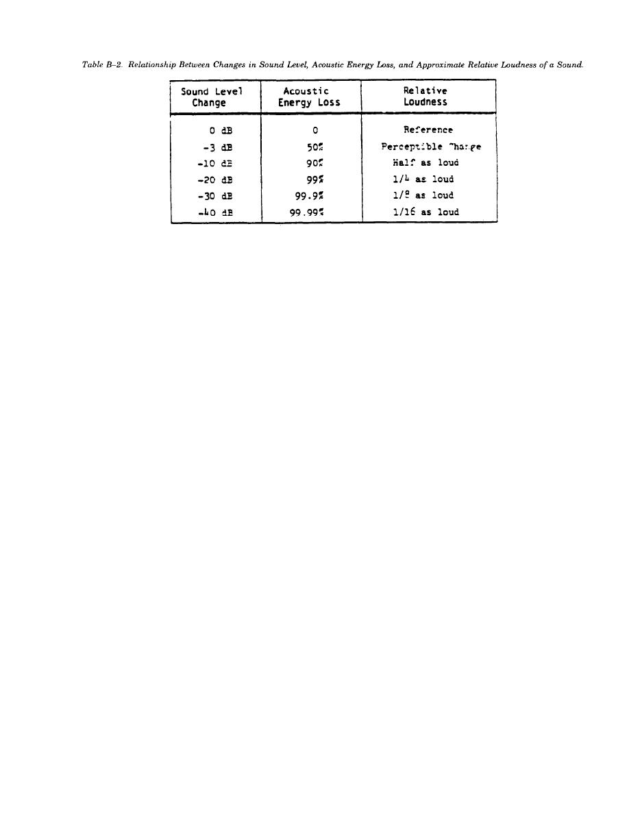
level changes, the resulting loss in acoustic power,
and the judgment of relative loudness of the
isolator mount when loaded. An isolator mount
might be an array of steel springs, neoprene-in-
changes. Toward the bottom of the table, it be-
shear mounts, or pads of compressed glass fiber or
comes clear that tremendous portions of the sound
power must be eliminated to achieve impressive
layers of ribbed or waffle-pattern neoprene pads.
amounts of noise reduction in terms of perceived
When the ratio of the driving frequency to the
loudness.
natural frequency is less than about 1.4, the
b. Sones and phons. Sones and phons are units
transmissibility goes above 1, which is the same as
used in calculating the relative loudness of sounds.
not having any vibration isolator. When the ratio
Sones are calculated from nomograms that interre-
of frequencies equals 1, that is, when the natural
late sound pressure levels and frequency, and
frequency of the mount coincides with the driving
phons are the summation of the sones by a special
frequency of the equipment, the system may go
addition procedure. The results are used in judging
into violent oscillation, to the point of damage or
the relative loudness of sounds, as in "a 50-phon
danger, unless the system is restrained by a
motorcycle would be judged louder than a 40-phon
damping or snubbing mechanism. Usually, the
motorcycle." When the values are reduced to phon
driver (the operating equipment) moves so quickly
ratings, the frequency characteristics and the
through this unique speed condition that there is
sound pressure level data have become detached,
no danger, but for large, heavy equipment that
and the noise control analyst or engineer has no
builds up speed slowly or runs downs slowly, this
concrete data for designing noise control treat-
is a special problem that must be handled. At
ments. Sones and phons are not used in this
higher driving speeds, the ratio of frequencies
manual, and their use for noise control purposes is
exceeds 1.4 and the mounting system begins to
of little value. When offered data in sones and
provide vibration isolation, that is, to reduce the
phons, the noise control engineer should request
force reduce the force transmitted into the floor or
the original octave or 1/3 octave band sound
other supported structure. The larger the ratio of
pressure level data, from which the sones and
frequencies, the more effective the isolation
mount.
phons were calculated.
a. Isolation efficiency. An isolation mounting
B-11. Vibration Transmissibility.
system that has a calculated transmissibility, say,
of 0.05 on figure B-2 is often described as having
A transmissibility curve is often used to indicate
an "isolation efficiency" of 95 percent. A transmis-
the general behavior of a vibration-isolated sys-
sibility of 0.02 corresponds to 98 percent isolation
tem. Transmissibility is roughly defined as the
efficiency, and so on. Strict interpretation of trans-
ratio of the force transmitted through the isolated
missibility data and isolation efficiencies, however,
system to the supporting structure to the driving
must be adjusted for real-life situations.
force exerted by the piece of vibrating equipment.
b. Transmissibility limitations. The transmissi-
Figure B-2 is the transmissibility curve of a
bility curve implies that the mounted equipment
simple undamped single-degree-of-freedom system.
(i.e. equipment plus the isolators) are supported by
The forcing frequency is usually the lowest driving
a structure that is infinitely massive and infinitely
frequency of the vibrating system. For an 1800-
rigid. In most situations, this condition is not met.
rpm pump, for example, the lowest driving fre-
For example, the deflection of a concrete floor slab
quency is 1800/60 = 30 Hz. The natural frequency,
B-9


 Previous Page
