TM 5 - 8 0 5 - 4 / A F J M A N
32-1090
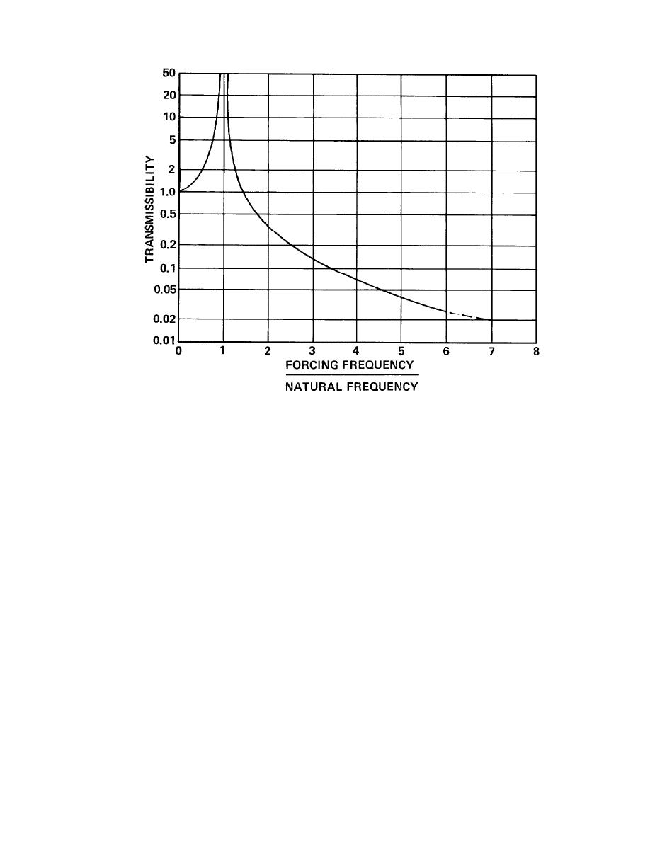
Figure B-2. Transmissibility of a Simple Undamped Single Degree-of-Freedom System.
under static load may fall in the range of 1/4 inch
(3) Difficulty of field measurement. In field
situations, the transmissibility of a mounting sys-
to 1/2 inch. This does not qualify as being infi-
tem is not easy to measure and check against a
nitely rigid. The isolation efficiency is reduced as
the static floor deflection increases. Therefore, the
specification. Yet the concept of transmissibility is
transmissibility values of figure B-2 should not be
at the heart of vibration isolation and should not
expected for any specific ratio of driving frequency
be discarded because of the above weakness. The
to natural frequency.
material that follows is based on the valuable
(1) Adjustment for floor deflection. In effect,
features of the transmissibility concept, but added
the natural frequency of the isolation system must
to it are some practical suggestions.
be made lower or the ratio of the two frequencies
B-12. Vibration Isolation Effectiveness.
made higher to compensate for the resilience of the
floor. This fact is especially true for upper floors of
With the transmissibility curve as a guide, three
a building and is even applicable to floor slabs
steps are added to arrive at a fairly practical
poured on grade (where the earth under the slab
approach toward estimating the expected effective-
acts as a spring). Only when equipment bases are
ness of an isolation mount.
supported on large extensive portions of bedrock
a. Static deflection of a mounting system. The
can the transmissibility curve be applied directly.
static deflection of a mount is simply the differ-
ence between the free-standing height of the un-
(2) Adjustment for floor span. This interpreta-
compressed, unloaded isolator and the height of
tion of the transmissibility curve is also applied to
floor structures having different column spacings.
the compressed isolator under its static load. This
difference is easily measured in the field or esti-
Usually, floors that have large column spacing,
mated from the manufacturer's catalog data. An
such as 50 to 60 feet, will have larger deflections
uncompressed 6 inch high steel spring that has a
that floors of shorter column-spacing, such as 20 to
compressed height of only 4 inches when installed
30 feet. To compensate, the natural frequency of
under a fan or pump is said to have a static
the mounting system is usually made lower as the
deflection of 2 inches. Static deflection data are
floor span increases. All of these factors are incor-
usually given in the catalogs of the isolator manu-
porated into the vibration isolation recommenda-
facturers or distributors. The data may be given in
tions in this chapter.
B-10


 Previous Page
