UFC 3-460-03
21 JANUARY 2003
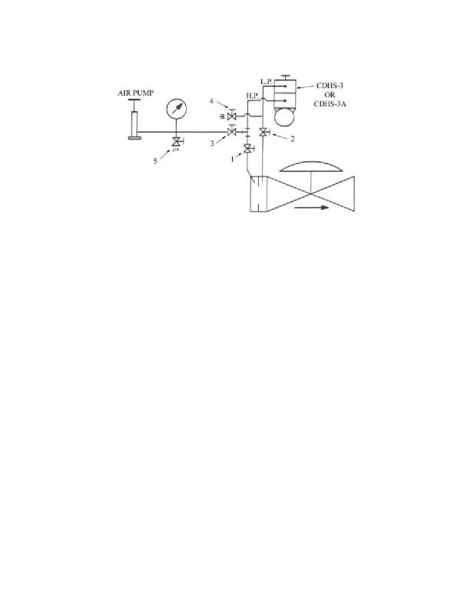
Figure A3.2. Shutoff Valves.
A3.2. Installing Valves. Shutoff valves (1 and 2) are in the high- and low-pressure sensing lines
between the orifice plate and the CDHS-3. Install valve 3 on a T in the high-pressure sensing line on the
CDHS-3 side of valve 1 to connect the air pump and pressure gauge. Install valve 4 on a T in the low-
pressure sensing line to vent the low-pressure side of the diaphragm to the atmosphere. Now the excess
flow control may be set without flowing fuel through the system.
A3.3. Set DP. To find the correct DP on the flow chart in Figure A3.1, move to the right across the
bottom line of the chart to find the flow rate (gallons per minute) at which your system typically
operates, then move vertically towards the top of the chart until the gallon-per-minute flow line
intersects the line drawn from the orifice bore size. From this intersection, follow the line to the left of
the chart and read the DP in psi. Use the DP figure from the chart in the following procedure:
A3.3.1. Close valves 1 and 2. Open valve 4 to vent the low-pressure side of the diaphragm to the
atmosphere. Connect a 0- to 15-psi gauge and air pump to shut off valve 3. Turn the adjustment
screw on the CDHS-3 clockwise until it bottoms out.
A3.3.2. Apply the pressure (psi) obtained from the flow chart to the high-pressure-sensing
connection. Turn the adjustment screw on the CDHS-3 counterclockwise until the control trips. After
the control trips, open valve 5 to bleed the pressure to 0 psi and reset the control. Repeat the
procedure several times to make sure the control trips at the correct pressure.
A3.3.3. To return the system to normal operation, remove the air pump and gauge, close and plug off
valves 3 and 4, and open valves l and 2. Remove the valve handles or safety-wire them in their
proper position to prevent tampering.
144


 Previous Page
